1.3 Switch Panels
Accessory loads hang off Garmin PowerSwitch boxes. Each box has six digitally switched outputs rated 30 A max per output, 100 A max per box, at 12-16 V. There are no branch breakers: the PowerSwitch output is the protection, so every branch conductor must be sized for 30 A, not for the load's expected draw.
Two panels are installed today, Rear Powerswitch (A) and Rear Powerswitch (B). Both are fed from the AUX battery through the SGP32 relay (see Batteries & Charging), and their circuits can run with the key off. A third panel, the Engine Bay Powerswitch, is planned.
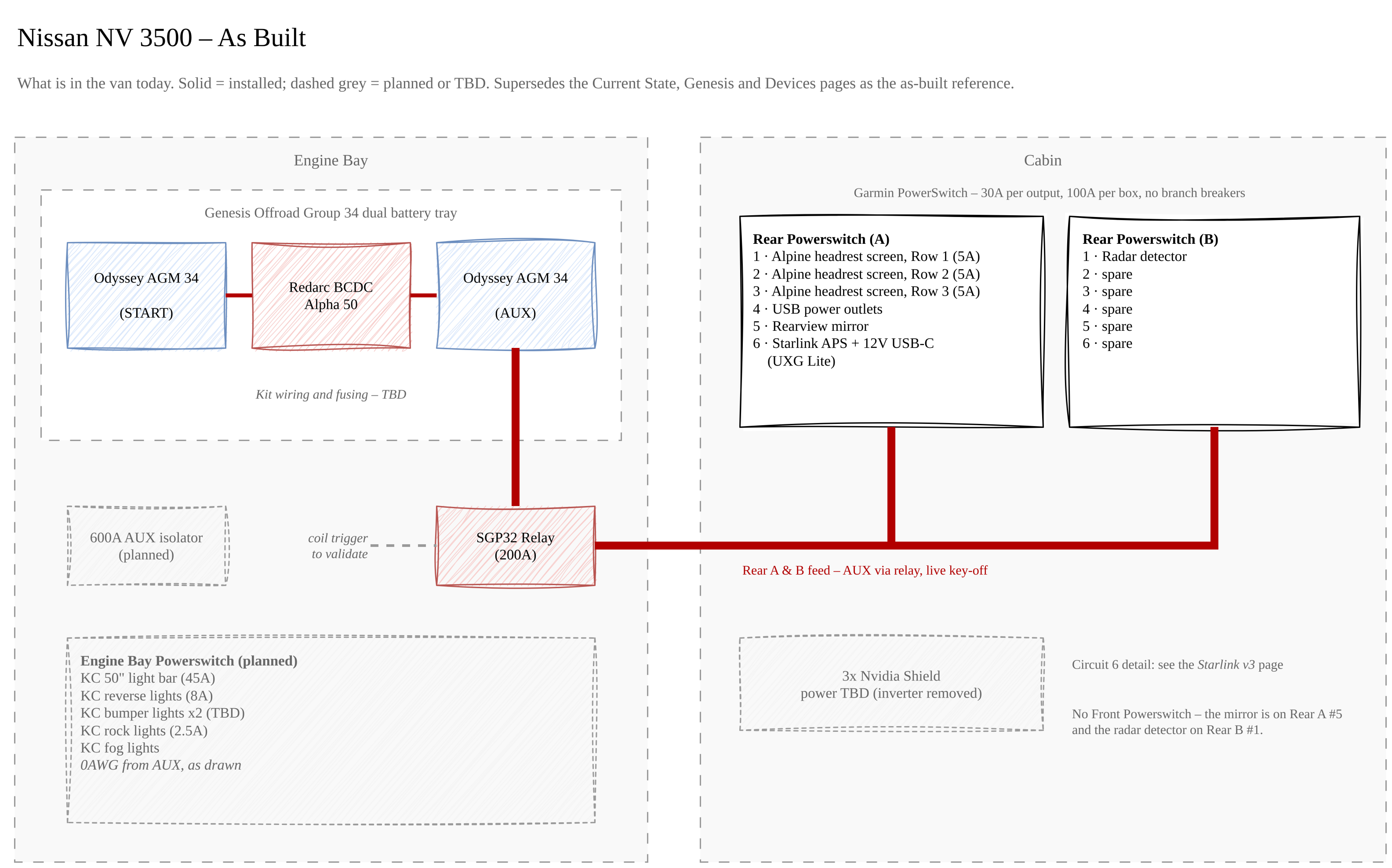
Diagram source: Van Electrical.drawio (page "As Built"); the image is regenerated from the draw.io file on each export.
Rear Powerswitch (A)
| Circuit | Load | Draw | Notes |
|---|---|---|---|
| 1 | Alpine PKG-RES3HDMI headrest screen, Row 1 | 5 A | HDMI from an Nvidia Shield |
| 2 | Alpine PKG-RES3HDMI headrest screen, Row 2 | 5 A | HDMI from an Nvidia Shield |
| 3 | Alpine PKG-RES3HDMI headrest screen, Row 3 | 5 A | HDMI from an Nvidia Shield |
| 4 | USB power outlets | TBD | |
| 5 | Rearview mirror | TBD | |
| 6 | Starlink Advanced Power Supply + 12 V USB-C outlet (UXG Lite) | Up to ~20 A + 3 A | Shared circuit; both switch together. See Starlink Power |
Nvidia Shields have no power source yet
The three Nvidia Shields feeding the headrest screens ran from the 1000 W inverter on the Current State drawing. The inverter has been removed, and how the Shields will be powered is TBD. The Devices redesign puts them on Rear Powerswitch (A) alongside the screens, but circuits 1-6 are all taken.
Rear Powerswitch (B)
| Circuit | Load | Draw | Notes |
|---|---|---|---|
| 1 | Radar detector | 2 A | |
| 2 | Spare | - | |
| 3 | Spare | - | |
| 4 | Spare | - | |
| 5 | Spare | - | |
| 6 | Spare | - |
The Devices drawing is not the as-built for Rear (B)
The Devices redesign loads Rear Powerswitch (B) with Starlink, USB power outlets, Twinkle Lights, and two 5 V USB-C buck converters feeding a UniFi USW-Flex-Mini and the UXG Lite. None of that is on (B): Starlink and the UXG Lite moved to Rear (A) circuit 6, the USW-Flex-Mini is not in use, and Twinkle Lights are not planned. The Devices drawing also shows a Front Powerswitch (Midland MXTX575, rearview mirror, radar detector) that does not exist. The mirror is on Rear (A) circuit 5 and the radar detector on Rear (B) circuit 1. The radio is a Midland MXT575, moving over from the Jeep LJ (owner, 2026-09-25); which circuit powers it is not decided.
Engine Bay Powerswitch (planned)
Not installed. As drawn, it is fed from the AUX battery on 0 AWG and carries the KC exterior lighting:
| Load | Draw | Control (per drawing legend) |
|---|---|---|
| KC 50" light bar | 45 A | Power switched |
| KC reverse lights | 8 A | Power switched & physical |
| KC bumper lights (x2) | TBD | Power switched |
| KC rock lights | 2.5 A | Power switched |
| KC fog lights | TBD | Power switched & physical |
The light bar exceeds one PowerSwitch output
A 45 A light bar is over the PowerSwitch's 30 A per-output limit. It cannot run straight from one output; it needs a relay triggered by the output, with its own fused feed. Resolve this before the panel is wired.
The drawings don't assign circuit numbers on this panel.
Outstanding Items
- Decide how the 3x Nvidia Shields are powered now that the inverter is out (Rear (B) has five spare circuits)
- Decide where the Shields' network connections land now that the USW-Flex-Mini is out
- Measure and record draw for Rear (A) circuits 4 (USB outlets) and 5 (rearview mirror)
- Record wire gauge and run length for every branch circuit; each must be rated for the 30 A output, not the load
- Confirm Rear Powerswitch (A)'s trigger inputs - the Current State drawing wires REVERSE and ACC to its control header (the rearview mirror likely uses REVERSE for its camera)
- Engine Bay Powerswitch: settle how the 45 A light bar is driven, record the KC bumper and fog light draw, and assign circuit numbers
- Update the Devices drawing, or mark it superseded, now that the As Built page exists