1.2 Batteries & Charging
Two Odyssey AGM Group 34 batteries, START and AUX, sit in a Genesis Offroad Group 34 dual battery tray in the engine bay, with a Redarc BCDC Alpha 50 DC-DC charger between them. The AUX battery feeds both rear switch panels through a 200 A SGP32 relay. The rear circuits, Starlink included, can run with the key off.
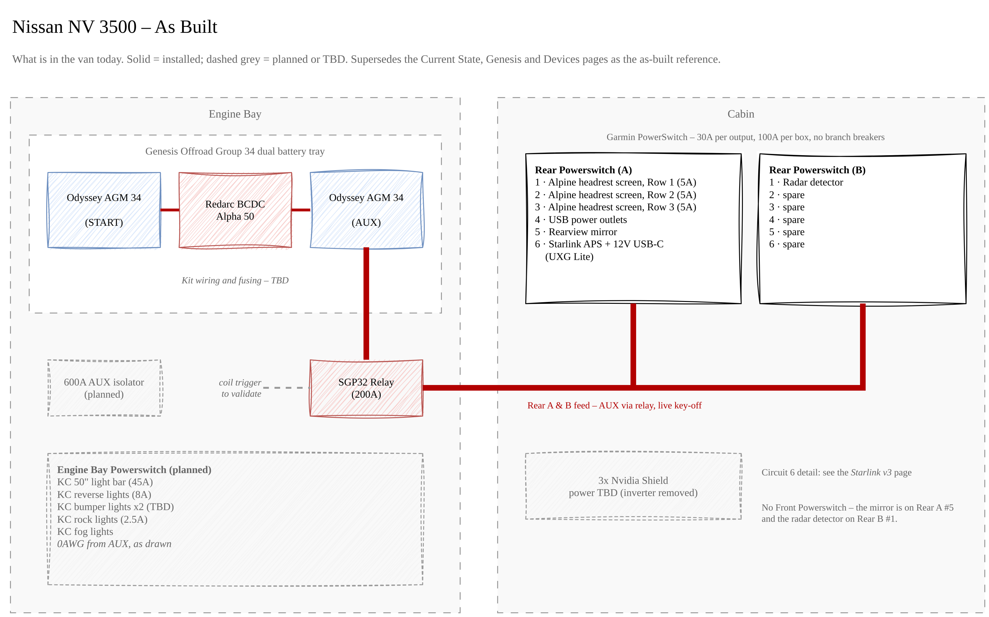
Diagram source: Van Electrical.drawio (page "As Built"); the image is regenerated from the draw.io file on each export.
Batteries
| Position | Battery | Role |
|---|---|---|
| START | Odyssey AGM Group 34 | Factory starting and vehicle loads, charged by the alternator |
| AUX | Odyssey AGM Group 34 | House battery for all accessory loads, charged from START through the BCDC |
Both batteries sit in the Genesis Offroad Group 34 dual battery tray.
Charging
| Item | Value |
|---|---|
| Charger | Redarc BCDC Alpha 50 (50 A DC-DC) |
| Input | START battery |
| Output | AUX battery |
| Mounting | Genesis Offroad dual battery tray |
| Wiring and fusing | Genesis kit wiring - gauges, fuse ratings and ignition sense TBD |
The Current State drawing is not the Genesis install
The Current State page of Van Electrical.drawio shows a discrete
install: a 70 A fuse on each side of the BCDC on 4 AWG runs of 6" max, an
ACC ignition trigger, and a temperature sensor on the AUX negative. The
van uses the Genesis kit's own wiring instead, so those values are not
the as-built and are not carried over here. Record the kit's actual fuse
ratings and gauges once checked - see Outstanding Items.
Rear panel feed - SGP32 relay
The 200 A SGP32 relay switches the AUX battery onto the feed for Rear Powerswitch (A) and (B). The rear panels and their circuits, including Starlink and the UXG Lite, can run with the key off, so the relay is not ignition-only. What triggers the relay has not been checked yet.
| Item | Value |
|---|---|
| Relay | SGP32, 200 A |
| Input | AUX battery (+) |
| Output | Rear Powerswitch (A) and Rear Powerswitch (B) |
| Coil trigger | To be validated - not ignition-only; rear circuits run key-off |
| Main feed fuse | TBD |
| Feed conductor | TBD - gauge and run length from the engine bay to the rear |
Repurposed from the inverter
This is the same relay that switched the old 1000 W inverter, when its coil was triggered from Rear Powerswitch (A) circuit 6. The inverter came out when Starlink moved to the Advanced Power Supply, and the relay now feeds the rear panels instead. The Current State and Genesis drawings still show the old inverter wiring.
Planned
These appear in the drawings but are not installed:
| Item | Source drawing | Notes |
|---|---|---|
| 600 A AUX isolator | Current State (between START and AUX) | Planned manual isolator for the AUX battery |
| Engine Bay Powerswitch | Current State, Genesis, Devices | Fed from AUX on 0 AWG as drawn. Loads listed in Switch Panels |
| 600 A rear cutoff | Current State, Genesis | Drawn as a manual cutoff on the Rear (A) & (B) feed. As built, the SGP32 relay does this job; decide whether a manual cutoff is still wanted |
Outstanding Items
- Record the Genesis kit's fuse ratings and cable gauges between START, the BCDC, and AUX
- Confirm how the BCDC Alpha 50 is ignition-sensed in the Genesis install (ACC wire vs. voltage sensing) and whether its temperature sensor is fitted
- Identify the fuse on the AUX → SGP32 relay → Rear (A) & (B) feed, and record its rating (Garmin's manual references a 125 A fuse on each PowerSwitch's supplied power cable)
- Record the gauge and run length of the rear panel feed
- Validate the SGP32 relay wiring: what energizes the coil, and confirm it feeds Rear Powerswitch (A) and (B)
- Specify the planned 600 A AUX isolator: part, location, and where it sits relative to the SGP32 relay
- Decide whether the manual 600 A rear cutoff is still wanted now that the SGP32 relay switches the feed
- Document the grounding scheme - the drawings show no ground returns