1.1.2 Alternator
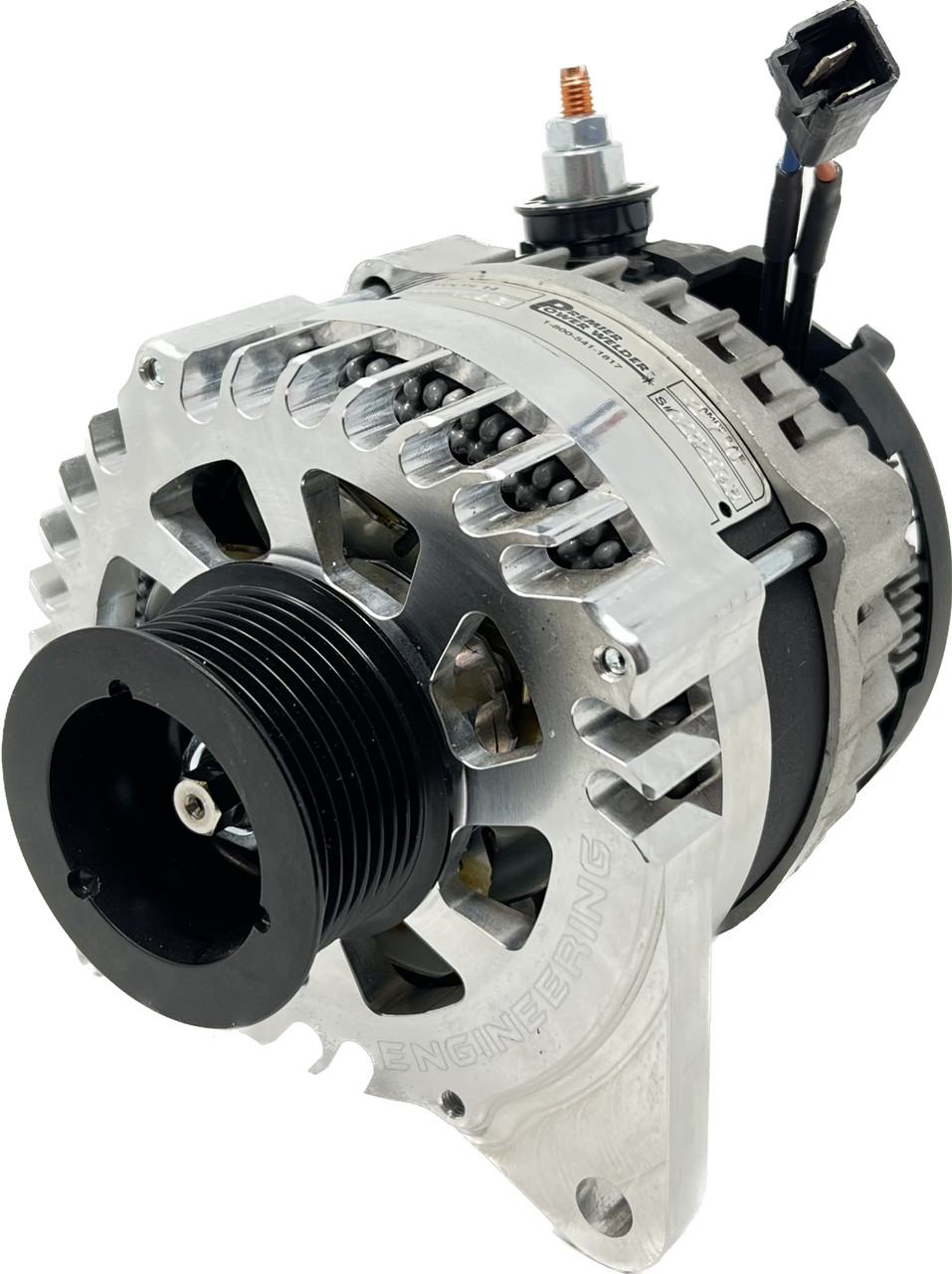
Type: High-Output Welding Alternator
Model: Premier Power Welder HO-C28
Manufacturer: Premier Power Welder
Product Page: Cummins R2.8 270A Alternator
Rating: 270 amps
Application: Cummins R2.8 Turbo Diesel
Price: $899.95
Specifications
- Output: 270A continuous
- Voltage: 12V (standard automotive)
- Application: Cummins R2.8 engines
- Type: High-output welding alternator
- SKU: HO-C28
System Configuration
Primary Function: Charges START battery and powers vehicle electrical systems
Output Capacity: 270A continuous (exceeds system maximum draw of ~326A with margin)
Mounting: Direct bolt-on replacement for Cummins R2.8
Wiring
| Connection | Destination | Notes |
|---|---|---|
| Positive Output | START battery+ (driver rear wheel well) | See START Battery Distribution for wire specs |
| Ground | Engine block | Bonded via alternator mounting bolts |
Ground Path: Alternator case → Engine block → Engine bay ground bus → START battery- (driver rear wheel well)
See START Battery Distribution for complete wire specifications (gauge, distance, voltage drop calculations).
Load Analysis
Alternator Capacity: 270A continuous
Worst Realistic Load: 201A (offroad scenario) = 69A margin (26% headroom)
The alternator supplies START battery loads plus BCDC charging. AUX battery loads (SwitchPros, ARB compressor, winch) do NOT draw from alternator.
See START Battery Load Analysis for complete scenario details.
Outstanding Items
High (3)
- JL Audio amp feed: 100A CB exceeds 4 AWG ampacity (95A @ 20°C) (#149) — The amp's battery feed is 4 AWG (95A continuous @ 20°C per the project reference table) protected by a 100A CB. The amp's internal 80A fuse is downstream and does not protect the battery-to-amp run against a chafe/short. This violates the project's "CB protects the wire" rule and is NOT covered by STANDARDS-EXCEPTIONS (which only sanctions the SwitchPros/SafetyHub 150A-on-2-AWG case).
- START+ auxiliary distribution busbar + breakers for relocated fan / iBooster / TCU (#135) — Relocating the radiator fan, iBooster, and TCU from the PMU to START-battery-direct adds three breaker-protected feeds. All three loads are forward (engine bay / transmission) while the START battery is rear, so the chosen architecture mirrors the AUX forward-feed pattern: a single master-protected feed forward to an engine-bay busbar rather than three long runs or ~9 stacked lugs on the battery post.
- Dakota Digital Panel Mounting (#39) — HDPE sheet dimensions and location for the Dakota Digital panel.
📋 Medium (10)
- SwitchPros Output Wire Lengths (#107) — Wire lengths for the 12 SwitchPros SP-1200 output circuits (front/cabin/rear/roof fan-out from the firewall) are currently 'Various / TBD'. Determine once final load mounting locations are fixed.
- Radio Ground Routing (#82) — Path for 14 AWG ground wires from GMRS / Intercom (dashboard) to START battery negative (driver rear wheel well) - direct grounds required for RF noise isolation
- BODY PDU Metri-Pack Pinout (#69) — J301-J306 connector pinout (military TM or reverse engineering)
- Alternator Voltage Regulator Set Point (#68) — Verify 14.2-14.4V for AGM batteries
- Alternator Output Terminal Size (#67) — Terminal size for 1/0 AWG lug selection
- RF Power Grommet Location (#66) — Grommet 6 location near battery for radio power
- Roof/Roll Bar Routing (#64) — Light bars, dome lights
- Cab to Cargo Routing (#63) — Rear lights, compressor, lockers
- Dash to Console Routing (#62) — Switch panels, USB, radio
- Firewall Grommet Circuits (#61) — Complete wire bundle lists
📝 Low (1)
- AUX battery− chassis-bond (rear frame rail) peak return current (#124) — Peak current through the AUX battery− → rear frame rail 2/0 chassis bond needs a proper derivation.
🔍 Verify (2)
- ARB compressor feed length: reconcile 8/10/12 ft and measure (#154) — Three different lengths are documented for the SafetyHub → ARB twin compressor feed: ~8 ft (wire-distance reference), ~10 ft (harness inventory H6), ~12 ft (SafetyHub circuit table). The SafetyHub is in the passenger rear wheel well and the compressor under the seat, so the spread doesn't change the 6 AWG sizing materially, but the figure should be measured and unified across the three files.
- Measured cable distances: START battery → relocated radiator fan / iBooster / TCU (#136) — The radiator fan, iBooster main, and TCU now feed from the START+ forward distribution busbar (engine bay) via a single master feed from the START battery (driver rear wheel well). Provisional gauges:
Build Tasks
- Determine alternator positive output terminal size (for 1/0 AWG lug selection) — see Vendor Inquiry below
- Verify alternator voltage regulator set point (14.2–14.4V is the correct AGM target;1 confirm the HO-C28 actually regulates there) — see Vendor Inquiry below
Vendor Inquiry — Premier Power Welder (draft)
Both open items above are answered by one email to Premier Power Welder:
Subject: HO-C28 (Cummins R2.8 270A) — output stud size & regulator set point

Hi Premier Power Welder,

I'm wiring the HO-C28 270A alternator (Cummins R2.8) into a dual-battery
truck and need two specs to finish the install:

1. Output terminal: what is the thread/stud size of the positive output
   post? I'm sizing a ring lug for 1/0 AWG cable and want the correct
   stud diameter (e.g. 1/4"-20, 5/16"-18, M8, etc.).

2. Voltage regulation: what is the regulator set point, and is it
   suitable for AGM batteries (target ~14.2-14.4V at the battery)? Is the
   regulator internal and fixed, or adjustable? My START battery is AGM.

Application: HO-C28 on a Cummins R2.8 Repower, charging an AGM start
battery (~850 CCA).

Thanks,
[name]
Related Documentation
- Batteries - START battery specifications (850 CCA)
- START battery Distribution - Alternator charging destination
- Grounding Architecture - Alternator ground path
- Wire Distance Reference - Alternator to battery routing distance
-
AGM batteries take an absorption/charge voltage of ~14.2–14.7V at the terminals (mfr range 14.0–14.7V), so the 14.2–14.4V target is correct; many stock regulators sit lower (13.8–14.0V) and undercharge AGM. The target is validated — what remains is confirming the HO-C28's actual set point (vendor or field measurement). General AGM charging references (Victron / battery-mfr guidance), accessed 2026-06-03. ↩