2.9.6 BIM-17-2 (Compass/Outside Temperature Module)
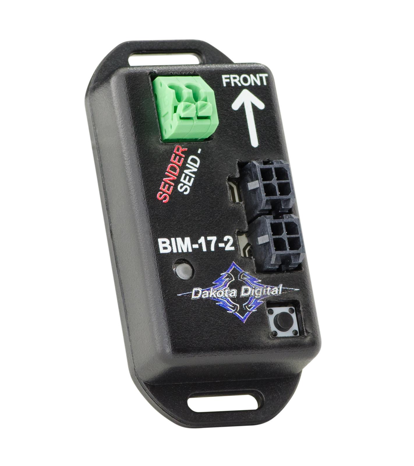
Type: Digital Compass / Outside Air Temperature Module
Model: BIM-17-2
Manufacturer: Dakota Digital
Product Page: Compass w/Outside Temperature Module
Overview
8-direction digital compass with outside air temperature sensor. Displays compass heading and outside temperature in dashboard message center.
Mounting: HDPE panel on firewall (behind dashboard)
Power: Via BIM/IO cable from HDX control box (no separate power wiring)
Specifications
Compass:
- Directions: 8-point (N, NE, E, SE, S, SW, W, NW)
- Internal Resolution: 1° (displayed as 8 directions)
- Calibration: Automatic via internal accelerometers
- Current Draw: Negligible — bus-powered via the HDX BIM/IO cable (no separate feed); draw is included in the HDX system budget on PMU OUT9 (25A cap, ~12A typ). Dakota Digital publishes no per-module current for these data modules (only power modules like the BIM-RGB, 7.4A, list a figure).
Temperature (SEN-15-1 Sender Included):
- Range: -40°F to 255°F
- Resolution: 1°F
- Warning Threshold: Configurable (-24°F to 40°F for low temp warning)
- Sensor Mounting: Grille area (behind grille, out of direct airflow)
Wiring
| Connection | Wire Gauge | Source | Destination | Distance | Notes |
|---|---|---|---|---|---|
| Constant | 18 AWG ✓ | Critical Cabin PDU Slot 6 (TBD #144) | BIM-17-2 power | ~1-2 ft | BIM CONSTANT power — may be bus-powered via BIM/IO cable instead |
| BIM/IO | Proprietary | HDX control box | BIM-17-2 input | Varies | Data via daisy-chain |
| Temp Probe | Sensor wire | BIM-17-2 | SEN-15-1 (grille area) | ~6-8 ft | Through firewall Grommet 6 |
Firewall Penetration:
- Temperature probe wire from BIM-17-2 (HDPE panel, cabin side) → Grommet 6 → grille area
- See Firewall Ingress for Grommet 6 routing details
Display Integration
Dashboard Message Center:
- Compass heading: 8-direction display (N, NE, E, SE, S, SW, W, NW)
- Outside temperature: Numeric display with degree symbol
- Low temperature warning: Configurable threshold (ice warning)
Compass vs. GPS-50-2 Comparison
Note: GPS-50-2 also provides compass functionality. Redundant with BIM-17-2 compass if both modules are used.
| Feature | BIM-17-2 Compass | GPS-50-2 Compass |
|---|---|---|
| Directions | 8-point (N, NE, E, etc.) | Digital heading |
| Source | Internal compass module | GPS satellite-based |
| Accuracy | 1° internal resolution | GPS-dependent |
| Stationary | Works when stopped | Requires vehicle movement |
| Calibration | Automatic | Automatic |
Recommendation:
- Use BIM-17-2 for primary compass (works at standstill)
- Use GPS-50-2 compass as backup or if BIM-17-2 not installed
Outstanding Items
🔴 Critical (2)
- Gauge cluster power architecture: PMU OUT9 vs Critical Cabin PDU slots (#144) — Two mutually exclusive power architectures are documented for the Dakota Digital gauge system and must be reconciled before the cluster can be wired:
- Dedicated brushless radiator-fan controller + coolant temp sensor selection (#134) — Moving the GM 84100128 radiator fan off the PMU (OUT2+3+4) onto START-battery-direct power requires a standalone brushless-fan PWM controller with its own coolant temperature sensor, independent of the PMU and the J1939 bus.
High (7)
- iBooster pedal ratio verification against 1.25" booster stroke (#301) — Verify the brake pedal ratio (approximately 4:1 per owner notes, 03-06 TJ/LJ auto pedal) against the Bosch Gen 2 iBooster's 1.25" stroke so the pedal reaches full booster travel without the cylinder bottoming, with the 1-1/8" Wilwood master and Super Duty calipers at all four corners. Bench-measure on assembly.
- Gear position display via J1939 (Turbolamik TCU → BIM-01-2 → HDX) (#110) — Verify that transmission gear position actually reaches the HDX dash over J1939 — and is displayed — without a discrete gear-position sender.
- Brake Proportioning Valve (#60) — Select adjustable proportioning valve for the rear disc circuit (iBooster has no integral proportioning); size on assembly
- Catch Can Mounting Bracket Point (#58) — Select engine bracketry attachment point for Mishimoto MMOCC-UB universal bracket
- AMOT Cable Firewall Grommet (#57) — Assign dedicated firewall grommet for AMOT push-pull cable pass-through (must not share with other cables)
- AMOT T-Handle Mounting Location (#56) — Select dash mounting position for Midwest Control 30-144-TTL-BH-3 (reachable belted, away from accidental contact)
- AMOT-to-Intake Adapters (#55) — Source NPT-to-hose fittings sized to match measured turbo inlet OD
📋 Medium (3)
- Horn button → PMU In 1 wiring path through steering column (#152) — PMU In 1 (horn request) lists "steering wheel button" as its source, and the horn page puts the button on the steering-wheel PTT bracket — but no wire path, gauge, or connector is defined for how the button contact reaches PMU In 1 through/around the steering column. Street-legal item with an under-specified signal path.
- iBooster Wiring Harness Selection (#105) — Select the Bosch iBooster (Gen 2) wiring harness: Tulay's Gen 2 universal (plug-and-play) vs EVcreate Gen 2 connector kit (DIY). Decision pending donor arrival and pigtail condition inspection. Tracked in the purchase tracker but was missing a TBD issue.
- Axle Brake Flex Hose Length (#86) — DOT (FMVSS 106) braided-stainless extended-length flex at each axle - length blocked on axle + suspension selection (Section 10); size to full droop, do not cut until ride height fixed
🔍 Verify (5)
- iBooster standby current spec (ignition-off test value) (#151) — The engine-systems testing checklist includes "Verify iBooster standby current within spec (ignition OFF)" but no standby-current spec value is documented anywhere (the brake-booster page does not state one). The test step cannot be completed as written.
- WAIT-to-start lamp polarity: ECM Pin 35 active-low vs HDX input active-high (#150) — ECM Pin 35 (WAIT lamp, yellow) is active LOW (~0V when WAIT on, ~+12V off); the HDX indicator input is documented as active HIGH. If wired without resolving this, the cold-start indicator reads inverted — and the documented cold-start procedure depends entirely on watching the WAIT lamp.
- Restomod Air HVAC integration — verify A/C request wiring to PMU In 9 + blower draw (#146) — The factory TJ HVAC is replaced by a custom Restomod Air electronic HVAC kit (ordered, owner-confirmed 2026-06-11) — this resolves the original "no A/C request source post-PCM-delete" gap. Restomod Air kits are fully electronic (servo-driven doors, no vacuum), and the control head generates the A/C request: compressor-engage output (12V) → trinary pressure switch (30/406 psi cutouts) → PMU In 9. PMU logic then drives OUT17 → compressor clutch.
- AMOT 4261M 2.8″ intake air-path connection OD / reducer coupler to 2.125″ turbo inlet (#129) — The 4261M02 is a wafer butterfly valve that sleeves into a 2.8″ (71 mm) nominal intake duct; the AMOT datasheet (4261M_Air_Shutoff_Valve_0119rev2) publishes only nominal size (71 mm), bore (61 mm / 2.4″), and overall envelope — not the air-path spigot/wafer OD or clamp interface. The NPT thread in part number
4261M02A027-AA(actuator code 27) is the pneumatic control port, not the air path. - Grid Heater Current (#42) — Design value 80A - verify via element resistance measurement during installation (~0.15 ohm @ 12V).
Build Tasks
- Determine outside temperature probe mounting location in grille area
- Determine primary compass source (BIM-17-2 vs GPS-50-2)
Related Documentation
- Dakota Digital System Overview - Complete system architecture
- Dashboard Cluster - Displays compass and temp data
- GPS-50-2 - Alternative compass source (GPS-based)
- Firewall Ingress - Grommet 6 routing for temperature probe