2.9.3 BIM-01-2-J1939 (J1939 CAN Interface)
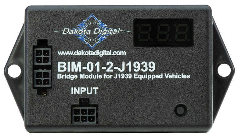
Type: J1939 CAN Bus Interface Module
Model: BIM-01-2-J1939
Manufacturer: Dakota Digital
Product Page: J-1939 CAN Interface
Manual: BIM-01-2-J1939 Manual
Overview
Interfaces Cummins R2.8 ECM J1939 CAN bus data with HDX instrument system. Provides engine parameters directly from ECM to dashboard cluster.
Mounting: HDPE panel on firewall (behind dashboard)
Power: Via BIM/IO cable from HDX control box (no separate power wiring)
Specifications
- Protocol: J1939 CAN bus only
- Compatible ECUs: Cummins R2.8, Mercury Racing SBF, BIGStuff EFI
- Wiring: CAN High, CAN Low (twisted pair)
- Power: Via BIM harness from HDX control
- Current Draw: Negligible — bus-powered via the HDX BIM/IO cable (no separate feed); draw is included in the HDX system budget on PMU OUT9 (25A cap, ~12A typ). Dakota Digital publishes no per-module current for these data modules (only power modules like the BIM-RGB, 7.4A, list a figure).
J1939 Data Available
Standard Parameters (Most Vehicles):
- Tachometer (RPM)
- Engine coolant temperature
- Check engine light / MIL indicator
Cummins R2.8 Specific (Expected):
- Oil pressure (SPN 100)
- Coolant temperature (SPN 110)
- Engine oil temperature (SPN 175)
- Engine hours
- Diagnostic trouble codes (DTCs)
Turbolamik TCU 2.0 (8HP70) Broadcast (UNVERIFIED — see issue #110):
- Gear position (PGN 61445 / ETC2 — SPN 523 current gear, SPN 524 selected gear) → intended to drive HDX GEAR display
- Transmission oil temperature
- Selected gear (Drive / Sport / Manual)
Gear display not yet vendor-confirmed
The no-sender design assumes (1) the Turbolamik TCU broadcasts ETC2 gear on J1939 and (2) the BIM-01-2 / HDX decodes and displays it. Neither is confirmed — Dakota Digital's J1939 BIM has historically been engine-parameter focused, so a gear/PRNDL channel may not exist even if the data is on the bus. If either is false, a discrete gear-position input (GSS-style sender or 8HP70 range switch) is required. Tracked in issue #110.
Potentially Available:
- Intake air temperature
- Fuel pressure
- Boost/MAP
- Air/fuel ratio
ECM Data Availability
Specific J1939 parameters vary by ECM configuration and vehicle application. Cummins R2.8 ECM should provide tachometer, coolant temp, oil pressure, and check engine light at minimum. Additional parameters depend on ECM programming and connected sensors.
Wiring
| Connection | Source | Destination | Wire Gauge | Notes |
|---|---|---|---|---|
| CAN High | Cummins body harness (cabin side) | BIM-01-2 CAN H | 18-22 AWG ✓ | Twisted pair with CAN Low |
| CAN Low | Cummins body harness (cabin side) | BIM-01-2 CAN L | 18-22 AWG ✓ | Twisted pair with CAN High |
| Constant | Critical Cabin PDU Slot 3 (TBD #144) | BIM-01-2 power | 18 AWG ✓ | BIM CONSTANT power — may be bus-powered via BIM/IO cable instead |
| BIM/IO | HDX control box | BIM-01-2 input | Proprietary | Daisy-chain to other BIM modules |
J1939 Connection:
- Cummins R2.8 body harness passes through firewall from engine bay to cabin
- CAN High/Low wires spliced on cabin side (non-invasive tap connectors)
- Short wire run from splice to BIM-01-2 on HDPE panel
- Turbolamik TCU 2.0 shares the same J1939 bus (tapped in engine bay) — both ECM and TCU broadcast to the BIM-01-2
Integration with Cummins R2.8
Available Signals:
- RPM → Tachometer
- Coolant temp (SPN 110) → Water temp gauge
- Oil pressure (SPN 100) → Oil pressure gauge
- Engine oil temp (SPN 175) → Available for display or logic (PMU oil cooler fan, OUT7)
- Check engine light / MIL → Dashboard warning indicator
Firewall Routing:
- Cummins body harness routes through firewall (engine bay → cabin)
- Tap J1939 CAN wires on cabin side of firewall
- See Firewall Ingress for Cummins harness routing details
Outstanding Items
🔴 Critical (2)
- Gauge cluster power architecture: PMU OUT9 vs Critical Cabin PDU slots (#144) — Two mutually exclusive power architectures are documented for the Dakota Digital gauge system and must be reconciled before the cluster can be wired:
- Dedicated brushless radiator-fan controller + coolant temp sensor selection (#134) — Moving the GM 84100128 radiator fan off the PMU (OUT2+3+4) onto START-battery-direct power requires a standalone brushless-fan PWM controller with its own coolant temperature sensor, independent of the PMU and the J1939 bus.
High (7)
- iBooster pedal ratio verification against 1.25" booster stroke (#301) — Verify the brake pedal ratio (approximately 4:1 per owner notes, 03-06 TJ/LJ auto pedal) against the Bosch Gen 2 iBooster's 1.25" stroke so the pedal reaches full booster travel without the cylinder bottoming, with the 1-1/8" Wilwood master and Super Duty calipers at all four corners. Bench-measure on assembly.
- Gear position display via J1939 (Turbolamik TCU → BIM-01-2 → HDX) (#110) — Verify that transmission gear position actually reaches the HDX dash over J1939 — and is displayed — without a discrete gear-position sender.
- Brake Proportioning Valve (#60) — Select adjustable proportioning valve for the rear disc circuit (iBooster has no integral proportioning); size on assembly
- Catch Can Mounting Bracket Point (#58) — Select engine bracketry attachment point for Mishimoto MMOCC-UB universal bracket
- AMOT Cable Firewall Grommet (#57) — Assign dedicated firewall grommet for AMOT push-pull cable pass-through (must not share with other cables)
- AMOT T-Handle Mounting Location (#56) — Select dash mounting position for Midwest Control 30-144-TTL-BH-3 (reachable belted, away from accidental contact)
- AMOT-to-Intake Adapters (#55) — Source NPT-to-hose fittings sized to match measured turbo inlet OD
📋 Medium (3)
- Horn button → PMU In 1 wiring path through steering column (#152) — PMU In 1 (horn request) lists "steering wheel button" as its source, and the horn page puts the button on the steering-wheel PTT bracket — but no wire path, gauge, or connector is defined for how the button contact reaches PMU In 1 through/around the steering column. Street-legal item with an under-specified signal path.
- iBooster Wiring Harness Selection (#105) — Select the Bosch iBooster (Gen 2) wiring harness: Tulay's Gen 2 universal (plug-and-play) vs EVcreate Gen 2 connector kit (DIY). Decision pending donor arrival and pigtail condition inspection. Tracked in the purchase tracker but was missing a TBD issue.
- Axle Brake Flex Hose Length (#86) — DOT (FMVSS 106) braided-stainless extended-length flex at each axle - length blocked on axle + suspension selection (Section 10); size to full droop, do not cut until ride height fixed
🔍 Verify (5)
- iBooster standby current spec (ignition-off test value) (#151) — The engine-systems testing checklist includes "Verify iBooster standby current within spec (ignition OFF)" but no standby-current spec value is documented anywhere (the brake-booster page does not state one). The test step cannot be completed as written.
- WAIT-to-start lamp polarity: ECM Pin 35 active-low vs HDX input active-high (#150) — ECM Pin 35 (WAIT lamp, yellow) is active LOW (~0V when WAIT on, ~+12V off); the HDX indicator input is documented as active HIGH. If wired without resolving this, the cold-start indicator reads inverted — and the documented cold-start procedure depends entirely on watching the WAIT lamp.
- Restomod Air HVAC integration — verify A/C request wiring to PMU In 9 + blower draw (#146) — The factory TJ HVAC is replaced by a custom Restomod Air electronic HVAC kit (ordered, owner-confirmed 2026-06-11) — this resolves the original "no A/C request source post-PCM-delete" gap. Restomod Air kits are fully electronic (servo-driven doors, no vacuum), and the control head generates the A/C request: compressor-engage output (12V) → trinary pressure switch (30/406 psi cutouts) → PMU In 9. PMU logic then drives OUT17 → compressor clutch.
- AMOT 4261M 2.8″ intake air-path connection OD / reducer coupler to 2.125″ turbo inlet (#129) — The 4261M02 is a wafer butterfly valve that sleeves into a 2.8″ (71 mm) nominal intake duct; the AMOT datasheet (4261M_Air_Shutoff_Valve_0119rev2) publishes only nominal size (71 mm), bore (61 mm / 2.4″), and overall envelope — not the air-path spigot/wafer OD or clamp interface. The NPT thread in part number
4261M02A027-AA(actuator code 27) is the pneumatic control port, not the air path. - Grid Heater Current (#42) — Design value 80A - verify via element resistance measurement during installation (~0.15 ohm @ 12V).
Build Tasks
- Confirm all J1939 parameters available from Cummins R2.8 ECM configuration
- Confirm Turbolamik TCU 2.0 broadcasts gear (ETC2 / SPN 523/524) on J1939 (issue #110)
- Confirm BIM-01-2 / HDX decodes and displays a gear value from J1939; else add discrete gear sender (issue #110)
Related Documentation
- Dakota Digital System Overview - Complete system architecture
- Dashboard Cluster - Displays J1939 data on gauges
- Cummins R2.8 ECM - J1939 CAN bus specifications
- Firewall Ingress - J1939 wire routing through firewall
- Radiator Fan System - Now uses a dedicated controller + own coolant sensor (no longer J1939/PMU-driven)