2.1 Starter System
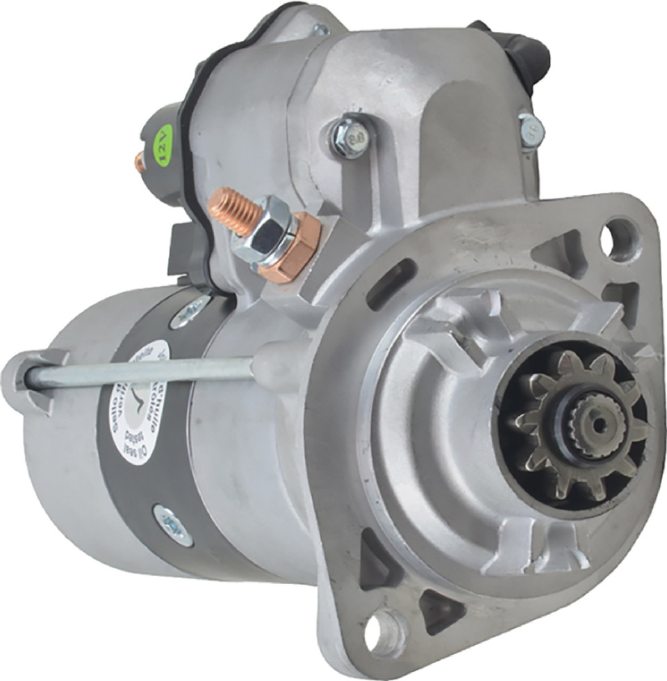
Type: High-Torque Diesel Starter
Model: DB Electrical 410-52442
Manufacturer: DB Electrical
Product Page: DB Electrical 410-52442
Voltage: 12V
Power: 2.7 kW
Rotation: Clockwise (CW)
Teeth: 10-tooth pinion
Mount Type: PLGR (Planetary Gear Reduction)
Weight: 19 lbs
Mounting: Engine block (PLGR mount)
Power Source: START battery+ direct connection (2/0 AWG)
OEM Cross-Reference:
- Cummins: 4996706
- Denso: 428000-7090, 438000-3110
- Isuzu: 5-128000-980
System Configuration
Control Method: Two-stage relay system
Main Power Source: START battery+ direct connection (see START Battery Distribution for wire specs)
Control Solenoid: Cole Hersee 24213 (200A continuous-duty)1
Safety Interlock: The crank signal (60A PURPLE START) comes solely from the PBS-I keyless module, which owns RFID authorization, the brake interlock, ACC/IGN/START sequencing, and the cold-start WAIT-to-Start lamp procedure — see Keyless Ignition. (An automatic crank lockout was evaluated and deferred — see the WAIT-to-Start Lockout Design Note.)
Battery Requirement: 800 CCA minimum (Odyssey PC1500 provides 850 CCA)
Wiring
| Circuit | Source | Destination | Wire Gauge | Current | Notes |
|---|---|---|---|---|---|
| Main Power | START battery+ | Starter solenoid battery post | 2/0 AWG | 400-600A | See START Battery Distribution for wire specs |
| Solenoid Power Tap | START battery post | Cole Hersee 24213 input | 10 AWG | 30-75A | ~2 ft |
| Start Signal | PBS-I PURPLE START output | Firewall Pin 15 → Cole Hersee coil+ | 16 AWG | ~0.69A | PBS-I output rated 60A but only Cole Hersee coil downstream1 |
| Solenoid Coil Ground | Cole Hersee 24213 coil- | Engine bay ground bus | 16 AWG | ~0.69A | ~3 ft |
| Solenoid Output | Cole Hersee 24213 output | Starter solenoid switch post | 10 AWG | 30-75A | ~2 ft |
| Ground Return | Starter case | Engine block → START battery- | 2/0 AWG | 400-600A | Via engine bay ground bus |
See Keyless Ignition for PBS-I power and brake input wiring.
Control Flow
PBS-I asserts PURPLE START  (fob auth + brake + sequence: see Keyless Ignition)
            ↓
PURPLE START → Firewall Pin 15 → Cole Hersee 24213 coil → Ground
            ↓
Cole Hersee main contacts close
            ↓
START battery → Cole Hersee output → Starter switch post → Bendix engages → cranks
            ↓
Engine starts → button released → Cole Hersee de-energizes → Bendix retracts
Starter Motor Terminals
Battery Post (M8 x 1.25 thread, qty 2):
- Main power from START battery (2/0 AWG)
- Power tap for control solenoid (10 AWG)
Switch Post (6.3mm flat male push-on):
- Trigger from Cole Hersee 24213 output (10 AWG, 30-75A)
Ground:
- Via starter mounting bolts to engine block
Cole Hersee 24213 Solenoid
Specifications:
- Rating: 200A continuous duty1
- Coil Voltage: 12V DC
- Coil Draw: ~0.69A (17.5 Ω coil @ 12V)1
- Mounting: Firewall (engine bay side)
Terminals:1
- Large Stud 1 (Input): 5/16"-24 copper power stud; from START battery post (10 AWG)
- Large Stud 2 (Output): 5/16"-24 copper power stud; to starter switch post (10 AWG; starter post is 6.3mm push-on)
- Small Stud 1 (Coil+): #10-32 steel stud; from Firewall Pin 15 (16 AWG, PBS-I PURPLE START)
- Small Stud 2 (Coil-): #10-32 steel stud; to engine bay ground bus (16-18 AWG)
Outstanding Items
🔴 Critical (2)
- Gauge cluster power architecture: PMU OUT9 vs Critical Cabin PDU slots (#144) — Two mutually exclusive power architectures are documented for the Dakota Digital gauge system and must be reconciled before the cluster can be wired:
- Dedicated brushless radiator-fan controller + coolant temp sensor selection (#134) — Moving the GM 84100128 radiator fan off the PMU (OUT2+3+4) onto START-battery-direct power requires a standalone brushless-fan PWM controller with its own coolant temperature sensor, independent of the PMU and the J1939 bus.
High (7)
- iBooster pedal ratio verification against 1.25" booster stroke (#301) — Verify the brake pedal ratio (approximately 4:1 per owner notes, 03-06 TJ/LJ auto pedal) against the Bosch Gen 2 iBooster's 1.25" stroke so the pedal reaches full booster travel without the cylinder bottoming, with the 1-1/8" Wilwood master and Super Duty calipers at all four corners. Bench-measure on assembly.
- Gear position display via J1939 (Turbolamik TCU → BIM-01-2 → HDX) (#110) — Verify that transmission gear position actually reaches the HDX dash over J1939 — and is displayed — without a discrete gear-position sender.
- Brake Proportioning Valve (#60) — Select adjustable proportioning valve for the rear disc circuit (iBooster has no integral proportioning); size on assembly
- Catch Can Mounting Bracket Point (#58) — Select engine bracketry attachment point for Mishimoto MMOCC-UB universal bracket
- AMOT Cable Firewall Grommet (#57) — Assign dedicated firewall grommet for AMOT push-pull cable pass-through (must not share with other cables)
- AMOT T-Handle Mounting Location (#56) — Select dash mounting position for Midwest Control 30-144-TTL-BH-3 (reachable belted, away from accidental contact)
- AMOT-to-Intake Adapters (#55) — Source NPT-to-hose fittings sized to match measured turbo inlet OD
📋 Medium (3)
- Horn button → PMU In 1 wiring path through steering column (#152) — PMU In 1 (horn request) lists "steering wheel button" as its source, and the horn page puts the button on the steering-wheel PTT bracket — but no wire path, gauge, or connector is defined for how the button contact reaches PMU In 1 through/around the steering column. Street-legal item with an under-specified signal path.
- iBooster Wiring Harness Selection (#105) — Select the Bosch iBooster (Gen 2) wiring harness: Tulay's Gen 2 universal (plug-and-play) vs EVcreate Gen 2 connector kit (DIY). Decision pending donor arrival and pigtail condition inspection. Tracked in the purchase tracker but was missing a TBD issue.
- Axle Brake Flex Hose Length (#86) — DOT (FMVSS 106) braided-stainless extended-length flex at each axle - length blocked on axle + suspension selection (Section 10); size to full droop, do not cut until ride height fixed
🔍 Verify (5)
- iBooster standby current spec (ignition-off test value) (#151) — The engine-systems testing checklist includes "Verify iBooster standby current within spec (ignition OFF)" but no standby-current spec value is documented anywhere (the brake-booster page does not state one). The test step cannot be completed as written.
- WAIT-to-start lamp polarity: ECM Pin 35 active-low vs HDX input active-high (#150) — ECM Pin 35 (WAIT lamp, yellow) is active LOW (~0V when WAIT on, ~+12V off); the HDX indicator input is documented as active HIGH. If wired without resolving this, the cold-start indicator reads inverted — and the documented cold-start procedure depends entirely on watching the WAIT lamp.
- Restomod Air HVAC integration — verify A/C request wiring to PMU In 9 + blower draw (#146) — The factory TJ HVAC is replaced by a custom Restomod Air electronic HVAC kit (ordered, owner-confirmed 2026-06-11) — this resolves the original "no A/C request source post-PCM-delete" gap. Restomod Air kits are fully electronic (servo-driven doors, no vacuum), and the control head generates the A/C request: compressor-engage output (12V) → trinary pressure switch (30/406 psi cutouts) → PMU In 9. PMU logic then drives OUT17 → compressor clutch.
- AMOT 4261M 2.8″ intake air-path connection OD / reducer coupler to 2.125″ turbo inlet (#129) — The 4261M02 is a wafer butterfly valve that sleeves into a 2.8″ (71 mm) nominal intake duct; the AMOT datasheet (4261M_Air_Shutoff_Valve_0119rev2) publishes only nominal size (71 mm), bore (61 mm / 2.4″), and overall envelope — not the air-path spigot/wafer OD or clamp interface. The NPT thread in part number
4261M02A027-AA(actuator code 27) is the pneumatic control port, not the air path. - Grid Heater Current (#42) — Design value 80A - verify via element resistance measurement during installation (~0.15 ohm @ 12V).
Related Documentation
- START battery Distribution - Main power source
- Firewall Ingress - Ignition START wire routing
- Engine Bay Ground Bus - Ground connections
- Power Generation - Battery specifications
- Wire Distance Reference - Starter to battery routing distances
- Keyless Ignition - PBS-I sources PURPLE START; cold-start wait via the WAIT-to-Start lamp
- WAIT-to-Start Lockout Design Note - Deferred automatic crank-lockout design, preserved for future revival
-
Littelfuse (Cole Hersee) 24213 continuous-duty SPST solenoid, product page / DigiKey #6347082. Rated 200A continuous with two 5/16"-24 copper power studs + two #10-32 steel coil studs; coil ~0.69A @ 12V (17.5 Ω). Corrects the earlier unsourced "85A / M8 / 6.3mm-push-on" figures (validated 2026-05-30). 200A is comfortably oversized for the ~10A starter-trigger path. ↩↩↩↩↩