1.2 START battery Distribution (Driver Rear Wheel Well)
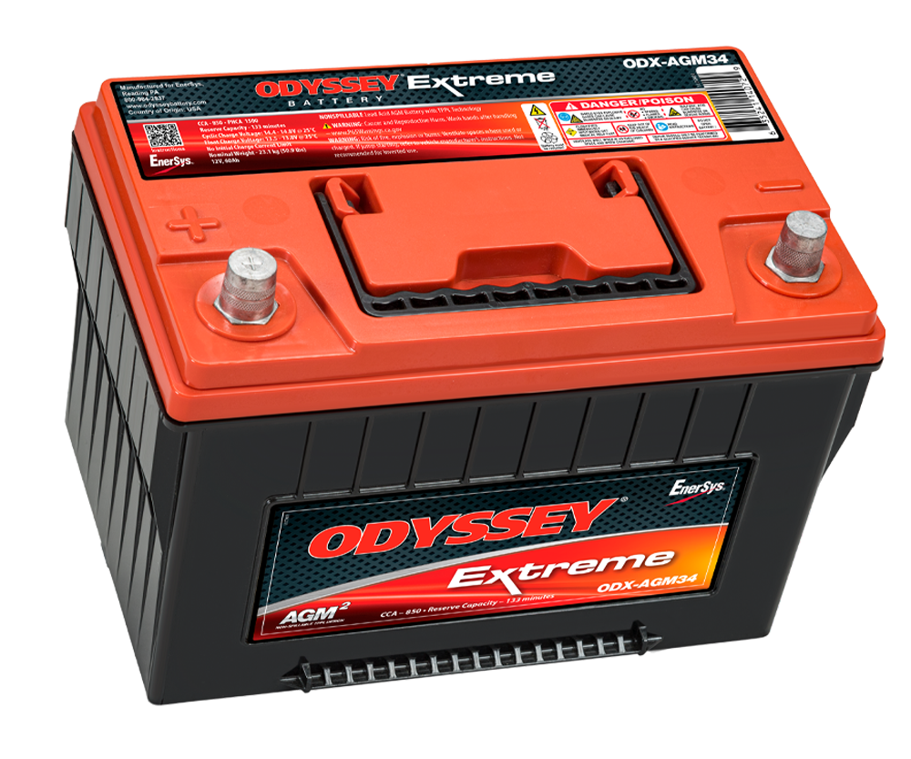
Overview
The START battery (driver rear wheel well) provides power for critical engine and safety systems:
- Direct high-current → Starter (no CB), alternator charging input (no CB)
- Circuit breaker protected → PMU (250A CB), BCDC (80A CB)
- START+ Forward Distribution Bus (150A master CB → single feed → engine-bay busbar) → radiator fan (60A), iBooster main (50A), TCU (25A) — relocated off the PMU
- Direct low-current → ECM, grid heater (fusible link protection)
See Circuit Breakers for complete CB specifications. All CBs mounted in rear wheel well within 7" of battery (code compliant).
Single Source of Truth
This page is the authoritative source for all START battery wire specs (gauge, distance, voltage drop). Component pages reference here. For battery specs see Section 1.1. For ground bus bars see Section 1.5.
START battery Positive Terminal (7 connections)
| Circuit | Destination | Wire Gauge | Distance | Current | Voltage Drop | Protection |
|---|---|---|---|---|---|---|
| Alternator | Engine bay | 2/0 AWG | 8 ft | 270A | 2.81% @ 60°C | None |
| Starter | Engine bay | 2/0 AWG | 6 ft | 400-600A | 1.9-3.9% @ 20°C | None |
| PMU24 | Engine bay | 2/0 AWG | ~7 ft | 250A max | 2.4% @ 60°C | 250A CB |
| START+ Forward Dist Bus | Engine bay | 2 AWG | ~8 ft | ~108A peak | 1.3% @ 60°C | 150A master CB |
| ECM | Engine bay | Per Cummins | Short | <5A | Negligible | Fusible link |
| Grid Heater | Engine bay | Per Cummins | Short | ~80A | Negligible | Fusible link |
| BCDC Alpha 50 | Passenger rear wheel well | 4 AWG | ~6 ft | 50A | 0.94% @ 20°C | 80A CB |
All circuit breakers mounted within 7" of battery (ABYC/NEC compliant). See Circuit Breakers.
START+ Forward Distribution Bus
The radiator fan, iBooster, and TCU were relocated off the PMU onto START-direct power. All three sit forward (engine bay / transmission) while the START battery is in the rear wheel well, so — mirroring the AUX forward-feed architecture — a single master-protected feed runs forward to an engine-bay busbar that fans out to the three loads on short local feeds. This keeps the long rear-to-front run to one heavy cable instead of three, and places each load's breaker near its load.
Busbar: Blue Sea 2105 MaxiBus (250A), engine bay, insulated cover — recommended; confirm with TBD #135 Master feed: 2 AWG, ~8 ft, 150A CB at battery post (<7")
| Load | Feed (from bus) | Wire Gauge | Distance | Current | Voltage Drop | Breaker |
|---|---|---|---|---|---|---|
| Radiator Fan | Radiator shroud | 4 AWG | short | 53A continuous | <1% @ 60°C1 | 60A |
| iBooster main | Firewall | 8 AWG | short | 40A peak / 0.25A idle | <0.5%1 | 50A |
| Turbolamik TCU | Transmission | 12 AWG | short | 15A continuous | <0.5%1 | 25A |
The master feed carries the combined load (~68A continuous, ~108A brief peak); voltage drop and breaker sizing are set on that single cable.1 The iBooster's separate ignition enable (~5A) is sourced from the Ignition Signal bus, not this bus. Fan speed is set by a dedicated fan controller (TBD #134) with its own coolant sensor, independent of the PMU and J1939.
Shared forward feed — intentional tradeoff
This is the same shared-feed tradeoff the AUX side accepts, and is more robust than the loads' former shared dependency on the PMU module. Each load keeps its own breaker. See Standards Exceptions for the full "no bus bar between battery and loads" exception rationale.
START battery Negative Terminal (6 connections)
| Circuit | Destination | Wire Gauge | Distance | Current | Voltage Drop |
|---|---|---|---|---|---|
| Engine Bay Ground Bus | Engine bay | 2/0 AWG | ~8 ft | 600A+ peak | <0.1V @ 60°C |
| ECM | Engine bay | 12 AWG | Short | <5A | Negligible |
| Grid Heater | Engine bay | Per Cummins | Short | ~80A | Negligible |
| AUX Battery | Passenger rear wheel well | 1/0 AWG | 5-6 ft | 75A max | <0.05V @ 20°C |
| G1 GMRS Radio | Dashboard | 10 AWG | ~8 ft | 15A TX | 1.2% @ 20°C |
| STX Intercom | Dashboard | 10 AWG | ~8 ft | 5A | 0.4% @ 20°C |
Radio grounds direct to battery for RF noise isolation. ECM/grid heater via Cummins harness to isolate from starter spikes.
START− intentionally has no local chassis bond — its chassis reference is the 2/0 AWG run to the Engine Bay Ground Bus (the rear frame chassis bond lives on the AUX− side). The 6 connections above are the complete, final set; an earlier "7 connections" count was an error.
Related Documentation
- Power Generation - Battery and alternator specifications
- Circuit Breakers - Complete CB specifications
- Grounding Architecture - Ground bus bars
- PMU24 - Power management unit
- BCDC Alpha 50 - DC-DC charger to AUX battery
- Starter System - Starter specifications
- Alternator - Charging system
- AUX battery Distribution - Aux/accessory battery system
-
Master feed 2 AWG @ ~108A brief peak (~68A continuous), ~8 ft, 60°C-derated (×1.2) ≈ 1.3% — sized on the combined load. Load feeds are short from the engine-bay bus, so per-load drop is negligible: fan 4 AWG @ 53A, iBooster 8 AWG @ 40A brief, TCU 12 AWG @ 15A. Final master-feed length and breaker selective-coordination pending TBD #136 and TBD #135. ↩↩↩↩