2.2 Brake Booster - Bosch iBooster Gen 2 + Wilwood MC
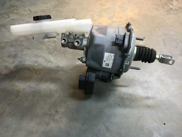
Type: Electric vacuum-independent brake booster + Wilwood tandem master
iBooster: Bosch iBooster Gen 2
Status: iBooster purchased (donor secured 2026-05-30)
iBooster Donor: Honda Accord Hybrid — Bosch iBooster Gen 21
Honda OEM Part Numbers: 46680-T3Z-A00 (booster module), 01469-TWA-A58 (MC/reservoir kit); MC mfr # 46100-TWA-A550-M11
Master Cylinder: Wilwood Tandem Compact — 1-1/8" bore (re-sized 2026-09-16 for the Super Duty calipers; see Master Cylinder section and Brakes)
MC Adapter: Back Bay Customs Wilwood iBooster Adapter — Honda Accord iBooster only (not Tesla); confirmed compatible with Wilwood 260-15542 (vendor, 2026-05-30); re-confirm against the 1-1/8" unit
Reservoirs: 2× Wilwood 260-16392 (4 oz anodized, remote) — vendor-confirmed OK with adapter2
Mounting: Direct firewall mount via booster's integral 4-stud flange (60×80mm M8, 80mm oriented vertical) + SendCutSend cabin-side backing plate
Power Source: START+ Forward Distribution Bus (50A CB, 40A main) — relocated off the PMU; ignition enable from Ignition Signal bus (~5A)
Wiring Harness: TBD #105 - Tulay's Gen 2 vs EVcreate Gen 2 kit
Overview
Electromechanical brake booster required for the Cummins R2.8 diesel (minimal manifold vacuum). The Honda Accord Hybrid donor delivers the same Bosch Gen 2 unit as the Tesla Model 3 with better DIY documentation and sourcing.
The Back Bay Customs adapter mates a Wilwood Tandem Compact master (1-1/8" bore; confirmed by the vendor against the 1.00" 260-15542) to the iBooster, solving the vertical-firewall reservoir-angle problem.
Vendor compatibility (Back Bay Customs / Adam, email 2026-05-30):
- The booster's 60×80mm firewall pattern12 must be mounted 80mm vertical. Back Bay's 80mm-horizontal adapter is out of stock — design around 80mm-vertical.
Specifications
iBooster
- Current: 40A peak (braking), 0.25A idle, 12mA standby
- Mounting Bolt Torque: 13 Nm (115 in-lb) - 2× nyloc nuts, 13mm (M8)3
Master Cylinder
Wilwood Tandem Compact, 1-1/8" bore — re-sized 2026-09-16 for the Super Duty calipers on the 1-ton axles, for knockback margin rather than steady-state caliper volume. Wilwood lists the 1-1/8" Tandem Compact as 260-15541; confirm the part number and re-confirm the Back Bay adapter (vendor-confirmed against the 1.00" 260-15542) before ordering. Sizing rationale is on the Brakes page.4 The original 1.00" selection is kept for the record.5
- Bore: 1-1/8" — Wilwood Tandem Compact (260-15541, confirm)4
- Stroke: 1.10" on the 260-15542; confirm for the 1-1/8" unit6
- Outlets: tandem (independent front/rear); thread 1/2-20 IF7
- Reservoir/inlet ports: remote feed; thread is an in-hand check, not a datasheet lookup7
Brake Hardware (downstream — MC bore design inputs)
- Front calipers: Ford Super Duty factory caliper on the Dana 60 front axle; piston area to be confirmed8
- Rear: disc — Ford Super Duty factory disc with drum-in-hat park brake, on the Sterling 10.5 rear axle; caliper piston area to be confirmed8
- Pedal: 03-06 TJ/LJ auto pedal (ratio bench-measured on assembly)
- These set the MC bore selection — see the Master Cylinder section and Brakes.
Plumbing
Reservoir → MC feed (low pressure): -3 AN PTFE braided — Wilwood 220-12993 (see Master Cylinder section). Gravity feed only; not a pressure circuit.
MC → calipers (high pressure) — hybrid hardline + axle flex. Baseline design; switchable to a more standard (or full-PTFE) approach later without changing the MC or its 1/2-20 IF outlets.
- Chassis runs: 3/16" copper-nickel (NiCopp / Cunifer) hardline off the MC's 1/2-20 IF outlets, 45° double (bubble) flare with inverted-flare fittings. DOT-approved for hydraulic brakes, will not corrode, and hand-bends/flares without a hydraulic bender.9 Copper-nickel is softer than steel, so sleeve in stainless spring "gravel guard" armor at exposed points and route inside the frame rail where possible.10
- Axle ends: DOT-compliant (FMVSS 106) braided-stainless flex hose at each axle, extended length sized to full suspension droop. Lengths are blocked on axle + suspension selection (Section 10 TBDs) — do not cut to length until ride height/articulation is fixed.11
- Hardline → flex transition: bulkhead fittings at each axle.
- Proportioning: the iBooster has no integral proportioning valve. Front disc + rear disc warrants an adjustable proportioning valve on the rear circuit (plus residual-pressure valves if needed); size on assembly. TBD #60
Alternative considered — full -3 AN PTFE braided throughout: field-repairable and common on non-street comp rigs, but not chosen for a street LJ — FMVSS 106 certification attaches to the finished assembly (DIY bulk-hose builds aren't road-certified) and the braid hides the liner from inspection.11 The hybrid keeps inspectable hardline on the long runs and isolates flex to the axles.
Parts List
| Item | Part # | Source | Status | Notes |
|---|---|---|---|---|
| iBooster + MC pull | Honda 46680-T3Z-A00 (+ 01469-TWA-A58) | eBay (listing #397546491129) | ✅ Purchased ($195, offer accepted 2026-05-30) | Honda Accord Hybrid Gen 2 donor; part #s confirmed on listing |
| Auto brake pedal assembly | 03-06 TJ/LJ auto pedal | eBay / junkyard | Ordered | Wider pedal pad than manual; stop-lamp switch + connector included on donor |
| MC adapter | Back Bay Customs | backbaycustoms.com | Confirmed vs 260-15542 (vendor, 2026-05-30); re-confirm against the 1-1/8" unit | Steel plate + pushrod spacer + nyloc nuts; Honda iBooster only |
| Master cylinder | Wilwood Tandem Compact 1-1/8" (260-15541, confirm) | Summit / Jegs | Re-sized 2026-09-16 for Super Duty calipers | Was 260-15542 1.00"; see Brakes |
| Reservoir (×2) | Wilwood 260-16392 | Summit / Jegs | Ready to order (vendor-confirmed OK) | 4 oz anodized, includes -3 AN fitting |
| Dual reservoir bracket | Wilwood 250-16393 | Summit / Jegs | Ready to order | Anodized billet, mounting screws incl. |
| Flexline (×2) | Wilwood 220-12993 | Summit / Jegs | Ready to order | 8" -3 AN, includes 11/16-20 adapter |
| Firewall mount (engine side) | iBooster integral 4-stud flange | Included w/ iBooster | Ships with donor | Bolts directly to firewall — 60×80mm M8 pattern (80mm vertical), ~62mm body neck through firewall13 |
| Firewall reinforcement (cabin side) | SendCutSend custom — see DXF | ~$15-30 | ⚠️ DXF needs redesign for 60×80mm pattern (currently drawn 72×72mm — see Outstanding Items) | 3/16" A36 steel, 152×152mm, 12mm corner radius, 9mm M8 holes, 64mm center bore. Zinc yellow plating |
| Wiring harness | TBD #105 | Tulay's or EVcreate | Decision pending donor arrival | Choice depends on donor pigtail condition |
| Brake hardline (caliper side) | 3/16" copper-nickel (NiCopp / Cunifer) coil | Summit / AGS / O'Reilly | Spec'd — order with fittings | DOT-approved; 45° double flare, 1/2-20 IF at MC; route inside frame rail |
| Hardline armor | 3/16" stainless spring gravel guard | 4LifetimeLines / Eastwood | Spec'd | Slide on before flaring; exposed runs |
| Inverted-flare fittings + bulkhead tees | 3/16" / -3 AN | Summit / Earl's / Wilwood | Spec'd | Hardline unions + hardline→flex transition at axles |
| Axle flex hoses | DOT braided stainless, extended length (TBD #86) | Goodridge / Rock Krawler / Synergy / Rusty's | ⚠️ Length blocked on axle + suspension (Section 10) | FMVSS 106; size to full droop |
| Adjustable proportioning valve | TBD #60 (Wilwood adjustable prop valve or equiv.) | Wilwood / Summit | TBD #60 | Rear circuit — iBooster has no integral proportioning |
Wiring
| Circuit | Wire Gauge | Source | Destination | Notes |
|---|---|---|---|---|
| Main Power | 8 AWG | START+ Forward Dist Bus (50A CB) | iBooster main connector | CONSTANT (safety requirement); START-direct, off the PMU |
| Ignition Enable | 16 AWG | Ignition Signal bus (fused terminal) | iBooster ignition input | SWITCHED (ignition RUN); ~5A; own firewall pin |
| Ground | 10 AWG | iBooster ground | Engine Bay Bus Stud 7 | Dedicated/redundant ground recommended (a bad ground disables assist) |
No ABS or ESP module. There is no hydraulic modulator downstream and nothing on CAN; the three circuits above are the whole electrical interface. The booster is expected to run on pedal position alone. That standalone behaviour comes from builder reports rather than a Bosch document, so confirm it with the harness vendor before committing to a harness (TBD #105).
Relocated off the PMU: Main power now comes from the START+ Forward Distribution Bus (50A CB) instead of PMU OUT1+10, and the ignition enable from the Ignition Signal bus instead of OUT19 — removing the brake booster's dependency on the PMU module. The booster retains its mechanical push-through, so a power loss is a hard pedal, not zero brakes.
See START Battery Distribution for the forward-bus feed and breaker specs.
Firewall Backing Plate
3/16" A36 steel sandwich plate that sits on the cabin side of the firewall, opposite the iBooster's integral 4-stud flange. Spreads cantilevered load across a larger area of firewall sheet metal to prevent fatigue cracking at the new M8 holes.
Geometry:
- 152mm × 152mm (6"×6") square, 12mm corner radius
- 4× 9mm M8 clearance holes on a 60mm (horizontal) × 80mm (vertical) rectangular pattern (80mm dimension vertical, per vendor)
- 64mm center pass-through bore (clearance for iBooster body neck protrusion)
- 3/16" (4.76mm) thickness
- Material: A36 mild steel
- Finish: zinc yellow plating (corrosion resistance for the cabin-side mounting area; also lets the plate stay visible-looking-intentional behind the dash)
DXF redesign required
The committed lj-ibooster-backing-plate.dxf was drawn for a 72×72mm square hole pattern (holes at ±36mm). Back Bay Customs confirmed (2026-05-30) the iBooster firewall pattern is actually 60×80mm rectangular (holes at ±30mm horizontal, ±40mm vertical), mounted 80mm-vertical. The DXF must be re-cut to the new pattern before ordering steel. The 152×152mm plate still provides ample edge margin (≥36mm at the ±40mm holes). Confirm the real hole spacing against the donor unit's studs during PLA test-fit before committing to steel.
CAD file: lj-ibooster-backing-plate.dxf (Fusion 360 — needs update to 60×80mm pattern)
Fabrication workflow:
- 3D-print a 1:1 PLA prototype first for trial fit against the LJ firewall + iBooster assembly. Use this to confirm hole spacing matches the donor unit's actual studs and that the 64mm bore clears the booster body neck.
- Verify clearance for cabin-side hardware (pedal box, HVAC blower, dash brackets) before committing to steel.
- If PLA mockup fits, upload the DXF to SendCutSend and order in 3/16" A36 steel with zinc yellow plating finish.
Brake Pedal Assembly
The factory LJ manual-trans pedal must be replaced with the 03-06 TJ/LJ automatic brake pedal to remove the clutch pedal and provide the correct pedal arm shape for an iBooster pushrod connection.
Signal/wiring impact: None new — the stop-lamp switch (Mopar 56045043AB) is identical on manual and auto brackets. The pedal swap inherits the existing brake-signal wiring already designed across three systems:
flowchart LR
    SUPPLY["Switched 12V<br/>(accessory feed)"]
    SWITCH["Stop-lamp switch<br/>Mopar 56045043AB<br/>(closes when pedal pressed)"]
    PMU["PMU In 2<br/>via Deutsch Pin 13"]
    LIGHTS["PMU OUT21 (7A)<br/>Brake lights"]
    PBSI["PBS-I Brake input<br/>(T-tapped with PMU In 2<br/>and Turbolamik TCU)"]
    TCU["Turbolamik TCU<br/>brake input"]

    SUPPLY --> SWITCH
    SWITCH -->|"Pole 1 tap"| PMU
    SWITCH -->|"Pole 1 tap"| PBSI
    SWITCH -->|"Pole 1 tap"| TCU
    PMU -->|"In 2 closes → OUT21 ON"| LIGHTS

    style SUPPLY fill:#ffd93d,color:#000
    style SWITCH fill:#d1d5db,color:#000
    style PMU fill:#a5d8ff,color:#000
    style LIGHTS fill:#d1d5db,color:#000
    style PBSI fill:#d1d5db,color:#000
style TCU fill:#d1d5db,color:#000- PMU is sensor + brain, not load path: PMU In 2 senses pedal-pressed; PMU OUT21 (7A) carries the actual brake-light current. Switch itself only handles logic-level (<1A).
- Single pole used: TJ/LJ 03-06 stop-lamp switches are 2-pole (4 pins). Pole 1 routes to PMU/PBS-I/TCU; Pole 2 was the factory cruise-deactivation pole — leave disconnected, not in this design.
- Splice location: Pole 1 output splices in the cabin into three branches — PMU In 2, PBS-I Brake input, and Turbolamik TCU brake input. Crank comes solely from the PBS-I PURPLE START output — brake switch Pole 1 does NOT connect to Firewall Pin 15.
See tail/brake (PMU lighting flow), starter (crank chain), and transmission (TCU brake input) for the downstream details.
Mechanical impact:
- Pushrod interface: Same on both pedal styles - iBooster clevis attaches at factory pushrod hole. Pivot-to-pushrod distance is identical; pedal arm shape differs (straight on auto vs. offset on manual) but does not affect the pedal ratio. Bench-measure before final assembly to confirm.
- BTSI provision: Auto pedal has a second boss for the factory floor-shifter BTSI solenoid - leave empty; Kilduff/Turbolamik handles unlock-from-Park electronically.
- Clutch removal: Clutch pedal, clutch master cylinder, and CMC firewall pass-through are no longer used. Plug the ~1.25" CMC hole in the firewall with a block-off plate or weld closed.
- Pedal pad: Auto pedal pad is wider - cosmetic only.
Donor checks:
- Stop-lamp switch + retaining clip present (or buy new Mopar 56045043AB)
- Pushrod hole bushing in good shape
- Pedal arm not bent/cracked at pivot
Installation Notes
- Firewall mounting strategy: Factory LJ vacuum booster holes are abandoned. The Honda Gen 2 iBooster bolts directly to the firewall via its own integral 4-stud flange (60×80mm M8 pattern, 80mm dimension vertical per Back Bay Customs; 62mm body neck through the firewall) — no separate steel bracket. Drill matching holes in the LJ firewall, then sandwich a SendCutSend 3/16" steel backing plate on the cabin side to distribute the cantilevered load and prevent fatigue cracking at the new holes. If an 80mm-horizontal orientation is ever required, Back Bay sells a re-orientation adapter (currently out of stock).
- Fallback paths: If integral flange has engine-bay packaging conflicts, fall back to (a) SendCutSend custom one-off firewall plate that re-patterns mounting holes, or (b) Back Bay Customs one-off commission — only worthwhile if they have access to an LJ for trial fit; without one, customer-measurement-blind design carries the same risk as SendCutSend at higher cost.
- Reservoir height: Mount reservoirs 4-6" above MC flange on firewall standoff for proper gravity feed. More than 6" risks hood clearance issues.
- Bench test before fab: Apply 12V ignition signal to the iBooster and verify motor cycles + pedal rod assists. Used iBoosters fail frequently.
- Cantilever support: Gen 2 is lighter than Gen 1 but on a vertical firewall through-hole the cantilevered load + Jeep vibration warrants a secondary front support point (inner fender or frame brace).
- Pushrod length (MC side): Back Bay's adapter pre-sets MC pushrod length - no adjustment required.
- Pushrod length (pedal side): Re-measure after auto-pedal swap; adjust per iBooster install kit instructions (Tulay's or EVcreate) before bleeding.
Installation Resources
- Wiring the iBooster - EVcreate
- Installing the iBooster - EVcreate
- iBooster Donor Vehicles - EVcreate
- Back Bay Customs Shop
Outstanding Items
🔴 Critical (2)
- Gauge cluster power architecture: PMU OUT9 vs Critical Cabin PDU slots (#144) — Two mutually exclusive power architectures are documented for the Dakota Digital gauge system and must be reconciled before the cluster can be wired:
- Dedicated brushless radiator-fan controller + coolant temp sensor selection (#134) — Moving the GM 84100128 radiator fan off the PMU (OUT2+3+4) onto START-battery-direct power requires a standalone brushless-fan PWM controller with its own coolant temperature sensor, independent of the PMU and the J1939 bus.
High (7)
- iBooster pedal ratio verification against 1.25" booster stroke (#301) — Verify the brake pedal ratio (approximately 4:1 per owner notes, 03-06 TJ/LJ auto pedal) against the Bosch Gen 2 iBooster's 1.25" stroke so the pedal reaches full booster travel without the cylinder bottoming, with the 1-1/8" Wilwood master and Super Duty calipers at all four corners. Bench-measure on assembly.
- Gear position display via J1939 (Turbolamik TCU → BIM-01-2 → HDX) (#110) — Verify that transmission gear position actually reaches the HDX dash over J1939 — and is displayed — without a discrete gear-position sender.
- Brake Proportioning Valve (#60) — Select adjustable proportioning valve for the rear disc circuit (iBooster has no integral proportioning); size on assembly
- Catch Can Mounting Bracket Point (#58) — Select engine bracketry attachment point for Mishimoto MMOCC-UB universal bracket
- AMOT Cable Firewall Grommet (#57) — Assign dedicated firewall grommet for AMOT push-pull cable pass-through (must not share with other cables)
- AMOT T-Handle Mounting Location (#56) — Select dash mounting position for Midwest Control 30-144-TTL-BH-3 (reachable belted, away from accidental contact)
- AMOT-to-Intake Adapters (#55) — Source NPT-to-hose fittings sized to match measured turbo inlet OD
📋 Medium (3)
- Horn button → PMU In 1 wiring path through steering column (#152) — PMU In 1 (horn request) lists "steering wheel button" as its source, and the horn page puts the button on the steering-wheel PTT bracket — but no wire path, gauge, or connector is defined for how the button contact reaches PMU In 1 through/around the steering column. Street-legal item with an under-specified signal path.
- iBooster Wiring Harness Selection (#105) — Select the Bosch iBooster (Gen 2) wiring harness: Tulay's Gen 2 universal (plug-and-play) vs EVcreate Gen 2 connector kit (DIY). Decision pending donor arrival and pigtail condition inspection. Tracked in the purchase tracker but was missing a TBD issue.
- Axle Brake Flex Hose Length (#86) — DOT (FMVSS 106) braided-stainless extended-length flex at each axle - length blocked on axle + suspension selection (Section 10); size to full droop, do not cut until ride height fixed
🔍 Verify (5)
- iBooster standby current spec (ignition-off test value) (#151) — The engine-systems testing checklist includes "Verify iBooster standby current within spec (ignition OFF)" but no standby-current spec value is documented anywhere (the brake-booster page does not state one). The test step cannot be completed as written.
- WAIT-to-start lamp polarity: ECM Pin 35 active-low vs HDX input active-high (#150) — ECM Pin 35 (WAIT lamp, yellow) is active LOW (~0V when WAIT on, ~+12V off); the HDX indicator input is documented as active HIGH. If wired without resolving this, the cold-start indicator reads inverted — and the documented cold-start procedure depends entirely on watching the WAIT lamp.
- Restomod Air HVAC integration — verify A/C request wiring to PMU In 9 + blower draw (#146) — The factory TJ HVAC is replaced by a custom Restomod Air electronic HVAC kit (ordered, owner-confirmed 2026-06-11) — this resolves the original "no A/C request source post-PCM-delete" gap. Restomod Air kits are fully electronic (servo-driven doors, no vacuum), and the control head generates the A/C request: compressor-engage output (12V) → trinary pressure switch (30/406 psi cutouts) → PMU In 9. PMU logic then drives OUT17 → compressor clutch.
- AMOT 4261M 2.8″ intake air-path connection OD / reducer coupler to 2.125″ turbo inlet (#129) — The 4261M02 is a wafer butterfly valve that sleeves into a 2.8″ (71 mm) nominal intake duct; the AMOT datasheet (4261M_Air_Shutoff_Valve_0119rev2) publishes only nominal size (71 mm), bore (61 mm / 2.4″), and overall envelope — not the air-path spigot/wafer OD or clamp interface. The NPT thread in part number
4261M02A027-AA(actuator code 27) is the pneumatic control port, not the air path. - Grid Heater Current (#42) — Design value 80A - verify via element resistance measurement during installation (~0.15 ohm @ 12V).
Build Tasks
Waiting on external action:
MC bore — resolved:
- Bench-measure TJ auto-pedal ratio on assembly — geometry/travel check only: confirm the ratio leaves MC stroke headroom (no long/sinking pedal) and the iBooster input rod gets full travel + full return. Does not affect the bore; pedal feel is drive-and-decide, not bench-tuned.
Backing plate redesign (vendor revised the firewall pattern):
- 🔴 Redesign
lj-ibooster-backing-plate.dxffrom the 72×72mm square pattern to the confirmed 60×80mm rectangular pattern (holes at ±30mm H / ±40mm V, 80mm vertical). Center bore (Ø64), plate size (152×152mm), and corner radius unchanged. Blocks the SendCutSend steel order. - Update firewall drilling jig/template to the 60×80mm pattern before mocking up
In progress:
- 3D-print PLA prototype of the revised backing plate (DXF) for trial fit; verify the 60×80mm hole spacing against donor studs and clearance for cabin-side hardware
Pending donor arrival (purchased 2026-05-30, listing #397546491129):
- Confirm casting part #s on the actual unit match the listing (46680-T3Z-A00 booster / 01469-TWA-A58 MC kit)
- Measure body-neck Ø against the 64mm backing-plate bore
- Bench test donor iBooster before any fab work (12V to ignition signal → motor cycles + pedal rod assists)
- Verify 4 mounting studs intact and body neck undamaged
- Photograph back face — finalize backing plate alignment + harness pigtail condition
- Select wiring harness: Tulay's Gen 2 universal (plug-and-play) vs EVcreate Gen 2 connector kit (DIY)
Pending mockup:
- Mock up iBooster + Wilwood MC assembly against LJ firewall (cardboard/3D-print) to verify engine-bay clearance before drilling
- Confirm flexline length after firewall mockup (220-12993 = 8", longer SKUs available if needed)
- Design / select reservoir standoff bracket location and height (4-6" above MC flange)
Ordering:
- Order master cylinder — Wilwood Tandem Compact 1-1/8" bore (260-15541, confirm part number) — re-sized for the Super Duty calipers
- Order plumbing: 2× 260-16392 reservoirs + 250-16393 dual bracket + 2× 220-12993 flexlines (vendor-confirmed)
- Order Back Bay Customs Wilwood MC adapter (confirmed vs 260-15542; re-confirm against the 1-1/8" unit)
- Confirm outlet threads on the 1-1/8" unit (plumbing assumes 1/2-20 IF at the MC)
- Verify the master cylinder reservoir-feed port thread on the actual MC in hand before buying any extra inlet fittings — Wilwood's datasheet leaves the inlet field blank (it's an integral-reservoir unit), so this is an in-hand check, not a datasheet lookup. Back Bay confirmed the remote reservoirs work with the adapter (Adam, 2026-05-30) and the 220-12993 is the flexline kit described to them.
Brake plumbing — caliper side (hybrid: copper-nickel hardline + axle flex):
- Order 3/16" copper-nickel hardline + inverted-flare fittings (1/2-20 IF at MC outlets) + stainless spring gravel-guard armor
- 🔵 Select extended-length DOT (FMVSS 106) braided flex hoses — blocked on axle + suspension selection (Section 10); size to full droop, do not cut until ride height is fixed
- Select adjustable proportioning valve for the rear circuit (iBooster has no integral proportioning) + any residual-pressure valves; size on assembly
- Confirm Super Duty front and rear caliper piston areas and check 1-1/8" MC stroke headroom (both axles changed)
- Plan routing: chassis runs inside the frame rail, bulkhead fittings at each axle for the hardline→flex transition
Fab + install:
- After PLA fit confirms: order SendCutSend backing plate in 3/16" A36 steel with zinc yellow plating
- Drill LJ firewall: 4× M8 clearance holes (60×80mm pattern, 80mm vertical) + 62mm center bore for booster shaft pass-through
- Plug clutch master cylinder firewall hole (~1.25" block-off plate or weld closure)
Related Documentation
- START+ Forward Distribution Bus - Main power feed + 50A breaker
- Ignition Signal Distribution - Ignition enable source
- Engine Bay Ground Bus - Stud 7 ground connection
- Firewall Ingress - Mounting and wire routing
-
Part numbers confirmed against the secured donor — eBay listing #397546491129 (offer accepted 2026-05-30): OE/OEM
46680-T3Z-A00+01469-TWA-A58, MC mfr #46100-TWA-A550-M1, Honda, made in Japan. Booster is the Bosch Gen 2 unit (EVcreate lists the Honda Accord under Gen 2; Back Bay adapter is Honda-Accord-only). Model year not asserted — the listing states none, and the physical part (not a catalog-year lookup) is the fitment reference. Verified 2026-05-30. ↩↩ -
Wilwood 260-16392 confirmed: 4.0 oz capacity, 9/16-18 × -3 AN hose connector (the -3 AN feed matches the Plumbing section). Source: Summit Racing / JEGS (checked 2026-05-30; thread figure is retailer-sourced). ↩
-
M8 studs (confirmed by EVcreate); Honda's power-brake-booster mounting-nut torque is ~115 in-lb / 13 Nm across Accord generations (TorqueSpec Database — Accord 2003-2007). Honda publishes no Gen 2 iBooster-specific figure. Not to be confused with the Bosch 16 Nm M12×1 brake-line nut. Verified 2026-05-30. ↩
-
Owner decision, 2026-09-16 — bore raised to 1-1/8" with the move to Ford Super Duty calipers front and rear (Dana 60 / Sterling 10.5 axles), sized for knockback margin. Supersedes the 1.00" selection recorded in the next footnote. ↩↩
-
Superseded 2026-09-16 (bore now 1-1/8"; see the Brakes page). Original 1.00" rationale: Wilwood 260-15542-BK = 1.00" bore (the 1.125" Tandem Compact is 260-15541). Sized to the brake hardware: TJ Rubicon front calipers (2.595" piston, ~5.29 sq in each) + rear disc, targeting standard/light pedal effort. The factory TJ master is itself a 1.00" bore Mopar matched to these calipers (TJ community); at 1.00" × 1.10" stroke (0.86 cu in/circuit) worst-case caliper fill leaves ~50% stroke headroom. A 1.125" bore would raise pedal effort and only benefits high-volume multi-piston calipers (not used here). 1.00"/260-15542 is also the part Back Bay confirmed the adapter against. Pedal ratio is a bench geometry/travel check on assembly, not a bore input. Checked 2026-05-30. ↩
-
Wilwood 260-15542 official page lists stroke 1.10" (checked 2026-05-30). ↩
-
Outlets 1/2-20 IF per Wilwood's 260-15542-BK page (outlet 1: 3/8-24 IF or 1/2-20 IF; outlet 2: 3/8-24 IF or 9/16-18 IF). The 260-15542 is an integral-reservoir unit and Wilwood's datasheet leaves the inlet thread blank, so the reservoir-feed thread is verified on the part in hand. Back Bay confirmed the remote reservoirs work with the adapter (2026-05-30); the 220-12993 flexline is the kit described to them. Checked 2026-06-01. ↩↩
-
Brake hardware changed 2026-09-16 with the move to Ford Super Duty axles front (Dana 60) and rear (Sterling 10.5): factory Super Duty calipers and rotors at all four corners with PowerStop Z36 pads and rotors, and a drum-in-hat park brake in the rear. The earlier inputs (TJ Rubicon front caliper, 2.595" piston per replacement-parts data, checked 2026-05-30; TJ rear disc + PowerStop rotors, seller-confirmed 2026-05-31) no longer apply. Confirm the Super Duty caliper piston areas and check the 1-1/8" bore stroke headroom before ordering fittings. ↩↩
-
Copper-nickel (NiCopp / Cunifer / cupronickel) brake tubing is DOT-approved for hydraulic brake systems and has been in OE use since the 1970s (Volvo, Audi, Porsche). Strength comparable to steel, far better corrosion resistance, and bends ~58% easier than steel. Off-road trade-off: softer than steel, so less puncture-resistant — mitigate with spring armor. Sources: AGS NiCopp, BrakeConnect Cunifer. Checked 2026-06-01. ↩
-
Stainless spring "gravel guard" / brake-line armor slips over 3/16" hardline (install before flaring) to deflect rock and debris strikes; route lines inside the frame rail since underbody lines are the most exposed to rock hazard. Sources: 4LifetimeLines gravel guard, Eastwood brakeline armor. Checked 2026-06-01. ↩
-
FMVSS 106 (49 CFR 571.106) governs brake hose assemblies — it is a performance standard, not a material spec, so PTFE/braided-stainless hose can be DOT-compliant. Hydraulic brake hose must withstand 4,000 psi for 2 minutes without rupture; hose ≤1/8" inside diameter (e.g. -3 AN) is tested to 7,000 psi. Certification attaches to the completed assembly, and hose marketed "off-road use only" carries no DOT rating and is not for public-road use. Sources: eCFR 49 CFR 571.106, Intertek FMVSS 106. Checked 2026-06-01. ↩↩
-
Back Bay Customs (adapter maker, Adam), email 2026-05-30. Vendor-confirmed firewall bolt pattern (60×80mm); the original backing-plate DXF was cut to an earlier unsourced 72×72mm estimate and needs the redesign noted above. ↩
-
~62mm body-neck (firewall pass-through), corroborated by Back Bay Customs (vendor, 2026-05-30) and Gen 2 Accord iBooster retrofit measurements (retrofit community / EVcreate: 62mm center bore, ~6mm protrusion). Honda publishes no figure — measured, not datasheet. Confirm on the donor before the final firewall cut: the backing-plate bore is 64mm, ~2mm radial clearance over a 62mm neck. Checked 2026-05-30. ↩