1.3.3 BODY PDU
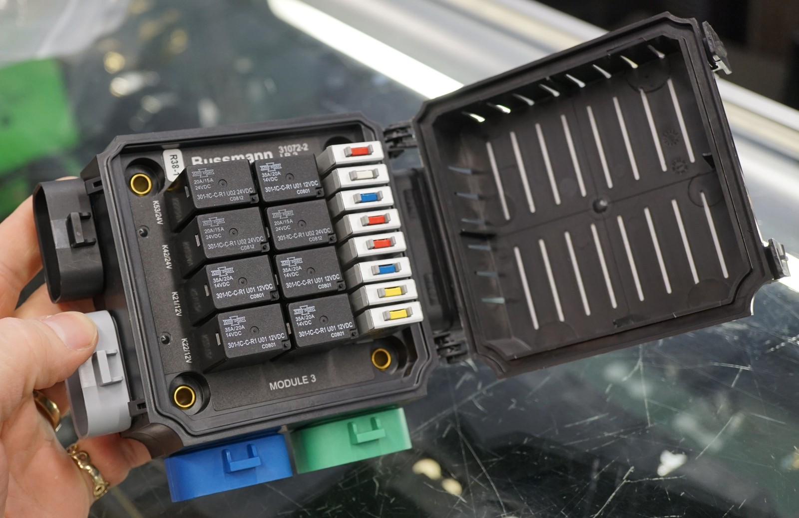
Type: Military-Spec Relay/Circuit Breaker Panel
Model: Bussmann LR-2
Part Number: Bussmann LR-2 panel, NSN 6110-01-523-6374 (the 301-1C-C-R1 is the Song Chuan ISO 280 relay that populates it, not the panel)1
Manufacturer: Bussmann (Eaton)
Source: Military surplus (MRAP/LMTV truck)
eBay Listing: Bussmann LR-2 Relay Breaker Block
Mounting: Firewall - body side (cabin), passenger side
Power Source: Firewall CONSTANT bus via 100A CB (2 AWG, ~2 ft local — bus is fed from AUX battery through 300A master CB and 2/0 AWG forward feed)
Ground: Firewall Stud Bus Terminal 3 (14 AWG) - relay coil/logic reference only
Configuration: 8 circuit breaker positions + 8 relay positions
Input: Military-spec power studs (accepts up to 2 AWG wire)
Output: J301-J306 Metri-Pack connectors (military-spec sealed)
Protection: IP65+ sealed military-grade enclosure
Temperature Rating: Military spec (-40°F to 221°F typical)
Voltage: 12V DC (originally 12V/24V dual voltage)
Circuit Breaker Configuration
| CB Position | Original Military Label | Repurposed Circuit | Size | Gauge | Load | Relay | Notes |
|---|---|---|---|---|---|---|---|
| CB30 | CHEM DETECT | Fusion Head Unit | 15A | 14AWG | ~15A | - | CONSTANT power, ignition sense from bus bar |
| CB48 | ARCT CRAN | USB Charging Ports | 20A | 14AWG | ~13A | - | 2x Powerwerx PanelUSB-75W (78W each, 7.5A fuse ea) |
| CB39 | TRLR BO STOP | WolfBox Camera/Mirror | 10A | 16AWG | ~10A | - | Dash cam + backup camera |
| CB45 | IGNITION | Driver Heated Seat | 15A | 14AWG | 5A peak, 2A sustained | K21 | Manual switch → relay K21 → seat element |
| CB42 | 2WAY INTRCM | Passenger Heated Seat | 20A | 14AWG | 5A peak, 2A sustained | K22 | Manual switch → relay K22 → seat element |
| CB20 | RADIO | Cargo Lights | 10A | 16AWG | 4A | - | Switch on rear wheel well top |
| CB43 | TRANS ECU | Winch Control (CH4X4 dual-push) | 10A | 18AWG | ~3A peak per direction | - | CH4X4-TOY-D-WINIO dual-momentary push at dash → HDP24 pins 16/17 → contactor; Warn remote parallel at contactor |
| CB44 | TRLR LIGHT | [Available] | - | - | - | - | Future expansion |
Circuit Breaker Utilization: 7 of 8 used (1 available)
Relay Configuration
| Relay Position | Original Military Label | Repurposed Function | Voltage | Control | Notes |
|---|---|---|---|---|---|
| K21 | REAR LEFT LIGHT | Driver Heated Seat | 12V | Dash switch | Controls CB45 output to driver seat |
| K22 | REAR RIGHT LIGHT | Passenger Heated Seat | 12V | Dash switch | Controls CB42 output to passenger seat |
| K27 | TRAILER BO STOP | [Available] | 12V | - | Future expansion |
| K30 | TRAILER REAR LEFT | [Available] | 12V | - | Future expansion |
| K31 | TRAILER REAR RIGHT | [Available] | 12V | - | Future expansion |
| K53 | RADIO | [Available] | 24V→12V | - | Swap 24V (U02) → 12V Song Chuan 301-1C-C-R1-U011 |
| K40 | START DISABEL | [Available] | 24V→12V | - | Swap 24V (U02) → 12V Song Chuan 301-1C-C-R1-U011 |
| K42 | ENGINE PTO | [Available] | 24V→12V | - | Swap 24V (U02) → 12V Song Chuan 301-1C-C-R1-U011 |
Relay Utilization: 2 of 8 used, 6 available (3 require 12V relay replacement)
Total Load: ~54A maximum (Radio 15A + USB 13A + Camera 10A + Seats 10A peak + Winch control 2A + Cargo lights 4A)
Control: All circuits on CONSTANT power with trigger-wire or manual switch control for on/off
Communication Devices
G1 GMRS Radio and STX Intercom are powered from the PMU — GMRS on OUT6, Intercom on OUT20 — with direct grounds to the START battery− to minimize RF noise. See PMU Outputs. SafetyHub is an AUX-side device and powers neither.
Outstanding Items
High (3)
- JL Audio amp feed: 100A CB exceeds 4 AWG ampacity (95A @ 20°C) (#149) — The amp's battery feed is 4 AWG (95A continuous @ 20°C per the project reference table) protected by a 100A CB. The amp's internal 80A fuse is downstream and does not protect the battery-to-amp run against a chafe/short. This violates the project's "CB protects the wire" rule and is NOT covered by STANDARDS-EXCEPTIONS (which only sanctions the SwitchPros/SafetyHub 150A-on-2-AWG case).
- START+ auxiliary distribution busbar + breakers for relocated fan / iBooster / TCU (#135) — Relocating the radiator fan, iBooster, and TCU from the PMU to START-battery-direct adds three breaker-protected feeds. All three loads are forward (engine bay / transmission) while the START battery is rear, so the chosen architecture mirrors the AUX forward-feed pattern: a single master-protected feed forward to an engine-bay busbar rather than three long runs or ~9 stacked lugs on the battery post.
- Dakota Digital Panel Mounting (#39) — HDPE sheet dimensions and location for the Dakota Digital panel.
📋 Medium (10)
- SwitchPros Output Wire Lengths (#107) — Wire lengths for the 12 SwitchPros SP-1200 output circuits (front/cabin/rear/roof fan-out from the firewall) are currently 'Various / TBD'. Determine once final load mounting locations are fixed.
- Radio Ground Routing (#82) — Path for 14 AWG ground wires from GMRS / Intercom (dashboard) to START battery negative (driver rear wheel well) - direct grounds required for RF noise isolation
- BODY PDU Metri-Pack Pinout (#69) — J301-J306 connector pinout (military TM or reverse engineering)
- Alternator Voltage Regulator Set Point (#68) — Verify 14.2-14.4V for AGM batteries
- Alternator Output Terminal Size (#67) — Terminal size for 1/0 AWG lug selection
- RF Power Grommet Location (#66) — Grommet 6 location near battery for radio power
- Roof/Roll Bar Routing (#64) — Light bars, dome lights
- Cab to Cargo Routing (#63) — Rear lights, compressor, lockers
- Dash to Console Routing (#62) — Switch panels, USB, radio
- Firewall Grommet Circuits (#61) — Complete wire bundle lists
📝 Low (1)
- AUX battery− chassis-bond (rear frame rail) peak return current (#124) — Peak current through the AUX battery− → rear frame rail 2/0 chassis bond needs a proper derivation.
🔍 Verify (2)
- ARB compressor feed length: reconcile 8/10/12 ft and measure (#154) — Three different lengths are documented for the SafetyHub → ARB twin compressor feed: ~8 ft (wire-distance reference), ~10 ft (harness inventory H6), ~12 ft (SafetyHub circuit table). The SafetyHub is in the passenger rear wheel well and the compressor under the seat, so the spread doesn't change the 6 AWG sizing materially, but the figure should be measured and unified across the three files.
- Measured cable distances: START battery → relocated radiator fan / iBooster / TCU (#136) — The radiator fan, iBooster main, and TCU now feed from the START+ forward distribution busbar (engine bay) via a single master feed from the START battery (driver rear wheel well). Provisional gauges:
Build Tasks
- Identify pinout for J301-J306 Metri-Pack connectors (military TM manual or reverse engineering)
Design Notes:
- High-side switching: BODY PDU switches positive power to loads; load current returns through each load's own ground wire, NOT through the PDU. The PDU ground connection (~3A) is only for relay coils and internal logic.
- Heated seat current: 5A peak, 2A sustained per seat (verified with vendor)
- Military relays K21/K22 provide fault isolation and independent operation
- J301-J306 connectors require custom harness fabrication
Related Documentation
- AUX battery Distribution - Power source and circuit breaker (passenger rear wheel well)
- Circuit Breakers - 100A CB protection for LR-2 power feed
- Dashboard Controls - Physical switch panel layout
- Audio Systems - Fusion radio specifications
- Firewall Ingress - Power feed routing through firewall
-
The Bussmann LR-2 is the panel;
301-1C-C-R1is the Song Chuan ISO 280 (2.8 mm) relay that populates it, voltage-coded by suffix — U01 = 12 V, U02 = 24 V. K40/K42/K53 ship with 24 V (U02); the 12 V drop-in is the same relay in U01 trim (301-1C-C-R1-U01-12VDC— SPDT, 35 A, ISO 280, resistor-suppressed). Sources: ProWire 301-1C-C-R1-U01-12VDC, eBay LR-2 listing (U01/U02 = 12 V/24 V); accessed 2026-06-06. ↩↩↩↩