Turn Signals
Controller: Command Touch CT4 (SW1 = right turn, SW2 = left turn)
Power Source: PMU Out 13 (CONSTANT, via CT4)
Features: GPS auto-cancel, lane change mode, hazard function
Turn Signal Distribution
Each CT4 output (SW1 right, SW2 left) splices to three destinations:
| Destination | Load | Wire | Notes |
|---|---|---|---|
| Front turn signal | ~0.2A | 14 AWG | Fender-mounted LED |
| Maxbilt rear turn | ~0.3A | 16 AWG | Integrated tail light |
| RTL-S amber | 0.36A | Per RTL-S harness | Chase light turn function |
| Total per side | ~0.9A | Well under 10A CT4 output capacity |
Splice Location: Behind dash (accessible for service)
Front Turn Signals
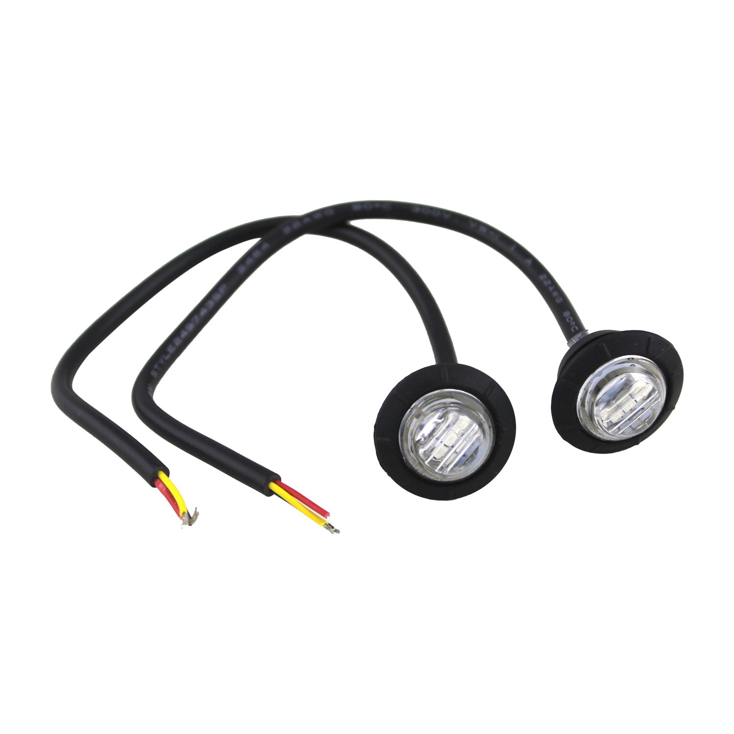
Type: Amber LED turn signals Quantity: 2 (left and right fenders) Function: Turn signal only (CT4 controlled) Part #: TBD #153 Size: 0.8" × 0.8" × 1.1" Draw: ~0.2A each (~0.4A total, estimated)
Wiring
| Function | Source | Wire | Current | Ampacity @60°C | Utilization |
|---|---|---|---|---|---|
| Right Turn | CT4 SW1 | BROWN, 14 AWG | ~0.2A | 20A | 1% |
| Left Turn | CT4 SW2 | RED, 14 AWG | ~0.2A | 20A | 1% |
Routing: CT4 (steering column) → firewall grommet → engine bay → fenders
Connections: Soldered with marine heat shrink (waterproof)
Rear Turn Signals
Rear turn signals are fed from the CT4 splice (see distribution table above):
- Maxbilt Round Trail Tail - YELLOW wire, see Tail/Brake/Reverse Lights
- RTL-S Chase Light - Yellow/Blue wires, see Chase Lights
Outstanding Items
📋 Medium (2)
- Front turn signal LED marker part selection (#153) — The turn-signals page documents front amber LED turn signals (qty 2, fender-mounted, ~0.8" × 0.8" × 1.1" envelope, CT4 SW1/SW2) with Part #: N/A. No part number exists anywhere in the docs and there is no purchase-tracker row — the wiring will be complete with no physical light to connect.
- Dome light rear-seat override: isolation needed to prevent backfeed into SwitchPros OUTPUT-4 (#148) — The rear-seat override wires the KC #6337 bracket switch in parallel with SwitchPros OUTPUT-4, fed from a 12V CONSTANT tap, with no isolation. Consequences as drawn: dome lights stay energized via the constant tap regardless of OUTPUT-4 state, and constant voltage is injected into the de-energized SP-1200 output.
Build Tasks
- Measure wire distance: CT4 → firewall → fenders (see Wire Distance Reference)
Related Documentation
- Command Touch CT4 - Controller programming and wiring
- Tail/Brake/Reverse Lights - Rear turn signal integration