1.3.2 Firewall CONSTANT Bus Bar
Type: Bus Bar
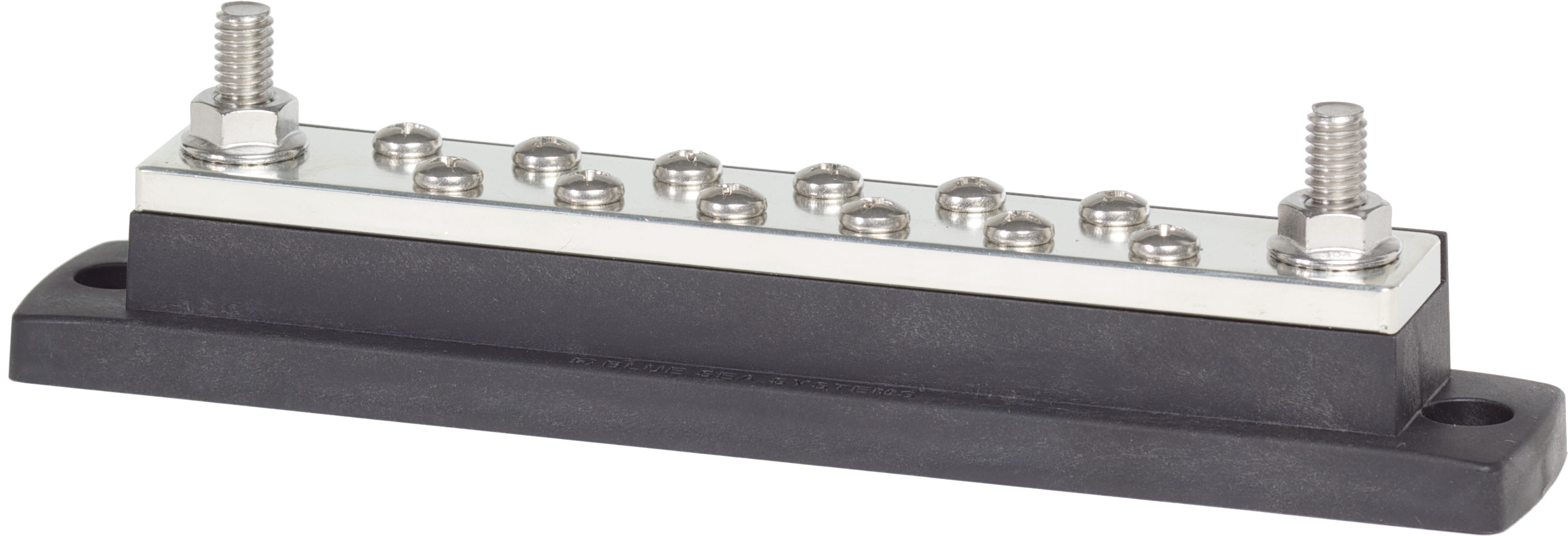
Model: Blue Sea 2105 MaxiBus (250A) or 2107 PowerBar (600A)
Manufacturer: Blue Sea Systems
Product Page: MaxiBus 250A
Overview
Forward distribution bus mounted on the firewall (passenger cabin side). Receives a single protected feed from the AUX battery and fans out to the cabin/firewall-mounted accessory controllers.
Location: Firewall (cabin side, passenger area), co-located with SwitchPros power module, BODY PDU, and JL Audio amplifier.
Two-Stage Distribution Architecture
The AUX battery has no local CONSTANT bus. Loads are distributed in two stages:
1. **AUX battery+ → inline CBs → 3 protected feeds** (forward to this firewall bus, local to SafetyHub, local to audio amp)
2. **Firewall CONSTANT bus → per-load CBs → 2 distribution controllers** (SwitchPros + BODY PDU)

The firewall bus is fed by a 2/0 AWG cable through a 300A master CB at the AUX battery (within 7" of battery terminal). This places power distribution *near the loads* (most SwitchPros outputs are forward, BODY PDU is at firewall; audio amp is fed directly from the AUX battery, not from this bus) and keeps the cabin trunk to a single heavy cable instead of multiple medium-gauge feeds.
Specifications
- Rating: 250A continuous (Blue Sea 2105) or 600A (2107 if oversized for future expansion)
- Terminals: 14× 1/4"-20 studs (2105) or 8× 3/8"-16 studs (2107)
- Wire Range: Up to 2/0 AWG (2105) or 4/0 AWG (2107)
- Features: Tin-plated copper, corrosion resistant
- Recommendation: 2105 is sufficient for ~154A combined load; 2107 if future expansion is anticipated
Input Feed (from AUX battery)
| From | Cable | Distance | Protection | Voltage Drop @ 200A | Notes |
|---|---|---|---|---|---|
| AUX battery+ | 2/0 AWG | ~13 ft | 300A CB at battery (<7") | ~2.0% @ 20°C | Routed via cabin trunk — see ⚠️ TBD #75 |
Load Distribution
| Connection | Wire Gauge | Distance | Voltage Drop | Protection | Load | Notes |
|---|---|---|---|---|---|---|
| Feed INPUT | 2/0 AWG | ~13 ft | <1.5% @ 20°C | 300A CB (at battery) | ~154A max | From AUX battery via cabin trunk |
| SwitchPros | 2 AWG | ~2 ft | <0.5% @ 20°C | 150A CB | ~100A max | Auxiliary lighting |
| BODY PDU | 2 AWG | ~2 ft | <0.5% @ 20°C | 100A CB | ~54A max | Cabin circuits |
Combined max realistic load: ~154A (well within 250A bus rating, comfortable in 600A bus)
Stud utilization: 3 of 14 used on 2105 (11 available), or 3 of 8 on 2107 (5 available)
Circuit Breakers (co-located with bus)
Both per-load CBs mount within 7" of the bus on a small bracket near the cluster:
| Load | CB Rating | Model | Notes |
|---|---|---|---|
| SwitchPros | 150A | Mechanical Products 174-S2-150-2 | 150% of max load |
| BODY PDU | 100A | Mechanical Products 174-S2-100-2 | 185% of max load |
See Circuit Breakers for full specs.
Related Documentation
Power Systems:
- AUX battery Distribution - Battery terminal connections and inline CBs
- Circuit Breakers - Full CB list (battery side + firewall side)
Connected Systems:
- SwitchPros RCR-Force 12 - Auxiliary lighting controller (power module at firewall)
- BODY PDU - Cabin convenience circuits
- Installation Checklist - Bus bar mounting procedure